Operation Manual
EDUS72-975
14
BRC1E71
3P243520-2C
8
English
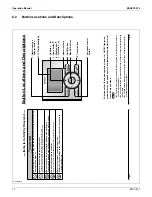
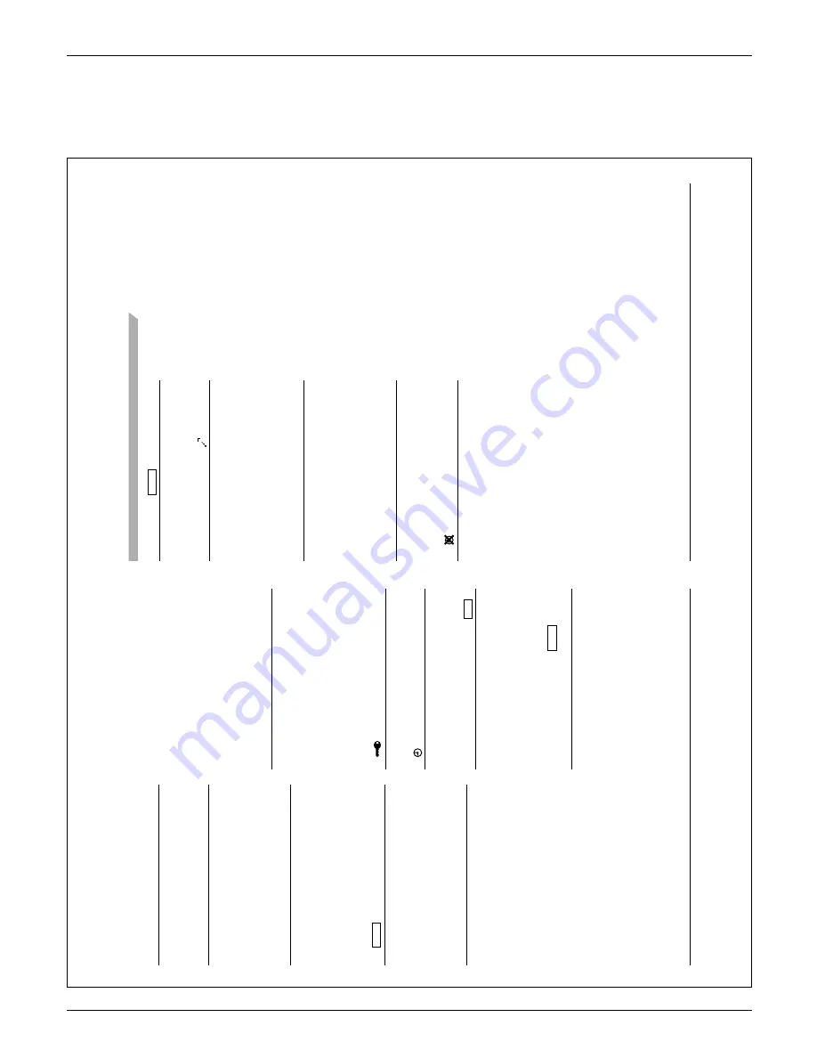
Names and Functions
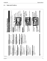
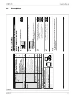
Setback “
1
1.
SETBACK
”
(See page 14.)
The setback icon fl
ashes when the unit is
Ɣ
turned on under the setback control.
Air Flow Direction “
12.
”
Displayed when the air fl
ow direction and
Ɣ
swing are set
(see page 23)
.
If the connected indoor unit model does not
Ɣ
include oscillating louvers this item will not
be displayed.
Current Day/T
ime (12/24 hour
13.
time display)
Displayed if the clock is set
Ɣ
(see page 39)
.
If the clock is not set, “ -- : -- ” will be
Ɣ
displayed.
12 hour time format is displayed by default.
Ɣ
Select 12/24 hour time display option in the
Ɣ
main menu under “Clock & Calendar”.
Detailed selection
14.
Displayed if the detailed display item is
Ɣ
selected
(see page 38)
.
Detailed items are not selected by default.
Ɣ
15. display
Displayed when the clock needs to be set.
Ɣ
The schedule function will not work unless
Ɣ
the clock is set.
01_EN_3P243520-2C.indd 8
8/27/2009 1:48:30 PM
English
7
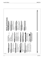
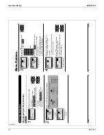
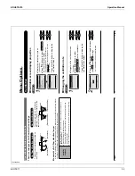
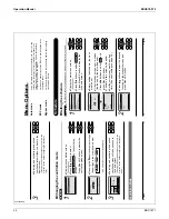
Operation mode
1.
Used to display the current operation
Ɣ
mode: Cool, Heat, V
ent, Fan, Dry or
Auto.
Fan Speed
2.
Used to display the fan speed that is set for
Ɣ
the indoor unit.
The fan speed will not be displayed if the
Ɣ
connected model does not have fan speed
control functionality
.
Setpoint display
3.
Used to display the setpoint for the indoor
Ɣ
unit.
Use the Celsius/Fahrenheit item in the
Ɣ
main menu to select the temperature unit
(Celsius or Fahrenheit).
Stand by for Defrost/Hot start
4.
“
ST
ANDBY
”
(See page 12.)
If ventilation icon is displayed in this fi
eld:
Indicates that an energy recovery ventilator
Ɣ
is connected.
For details, refer to the Operation Manual
of the ER
V
.
Message
5.
The following messages may be
displayed.
“This function is not available”
Displayed for a few seconds when an
Ɣ
operation button is pressed and the indoor
unit does not provide the corresponding
function.
In a remote control group, the message will
Ɣ
not appear if at least one of the indoor units
provides the corresponding function.
“Error: Push Menu button”
“W
arning: Push Menu button”
Displayed if an error or warning is detected
Ɣ
(see page 45)
.
“T
ime to clean fi
lter”
“T
ime to clean element”
“T
ime to clean fi
lter & element”
Displayed as a reminder when it is time to
Ɣ
clean the fi
lter or element
(see page 43).
V
entilation
6.
Displayed when a energy recovery
Ɣ
ventilator is connected.
V
entilation Mode icon.“
Ɣ
AUT
O
ER
V
ER
V
BYP
ASS
”
These icons indicate the current ventilation
mode (ER
V only) (AUT
O, ER
V
, BYP
ASS).
Air Purify ICON “
Ɣ
AIR
PURIFY
”
This icon indicates that the air purifying unit
(option) in operation.
7. display
(See page 18.)
Displayed when the key lock is set.
Ɣ
8. display
(See page 28.)
Displayed if the Schedule or Of
f timer is
Ɣ
enabled.
Under Centralized control “
9.
CENTRAL CONTROL
”
Displayed if the system is under the
Ɣ
management of a multi zone controller
(option) and the operation of the system
through the remote controller is limited.
Changeover controlled by the
10.
master indoor unit “
MASTER
CONTROLLED
”
(VR
V only)
Displayed when another indoor unit on the
Ɣ
system has the authority to change the
operation mode between cool and heat.
01_EN_3P243520-2C.indd 7
8/27/2009 1:48:29 PM
Содержание BRC1E71
Страница 1: ...AMERICAS...
Страница 8: ...EDUS72 975 Features BRC1E71 7 1 5 Other Features...


