background image


133 

Step 1  

Select 

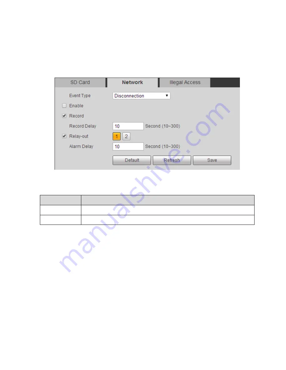
“Setup > Event > Abnormity > Network” and the system will display the interface of “Network”, 

which is shown in Figure 6-67.  

Note:  

The figure is an example of 

“Event Type” which is set as “Disconnection”.  


Figure 6-67 

Step 2  

It is to configure parameter info according to actual needs, please refer to sheet 6-37 and sheet 6-41. 

Parameter  

Note  

Event Type  

It includes disconnection and IP conflict.  

Enable  

Select “Enable” and it will trigger alarm when network is abnormal. 

Sheet 6-41 

Step 3  

Click 

“Save” to make config valid.  


6.5.4.3 

Illegal Access  

When the login password has been wrong for certain times, it will trigger alarm of illegal access.  

Step 1  

Select 

“Setup > Event > Abnormity > Illegal Access” and the system will display the interface of “Illegal 

Access

”, which is shown in Figure 6-68.  

Содержание DH-TPC-PT8320A

Страница 1: ...i Multi spectral Thermal Camera Web3 0 Operation Manual Version 1 0 0 ...

Страница 2: ...1 Bullet Camera 13 3 1 1 Setting Protocol 13 3 1 2 Setting Function 14 3 1 3 PTZ Control 17 3 2 Speed Dome and PTZ 19 3 2 1 Setting Protocol 19 3 2 2 Setting Function 20 3 2 3 PTZ Control 31 4 Playback 34 4 1 Video Playback 34 4 1 1 Play Control Bar 36 4 1 2 Playback Video 36 4 1 3 Video Clip 42 4 1 4 Assistant Function 43 4 2 Picture Playback 43 5 Report 48 6 Setup 50 6 1 Camera 50 6 1 1 Conditio...

Страница 3: ...4 2 Face Detection 115 6 4 3 Fire Warning 116 6 4 4 Cold Hot Spot Follow 119 6 4 5 Pic in Pic 121 6 4 6 Link Schedule 122 6 5 Event 123 6 5 1 Video Detect 123 6 5 2 Temperature Alarm 129 6 5 3 Alarm Setting 130 6 5 4 Abnormity 131 6 6 Temperature 134 6 6 1 Rule 134 6 6 2 Global 138 6 6 3 Heatmap 142 6 7 Storage Management 143 6 7 1 Schedule 143 6 7 2 Destination 149 6 7 3 Record control 152 6 8 Sy...

Страница 4: ...iv 6 8 5 Auto Maintenance 160 6 8 6 Upgrade 161 6 9 Information 161 6 9 1 Version 161 6 9 2 Log 162 6 9 3 Online User 163 7 Alarm 165 8 Log out 167 ...

Страница 5: ...v Important The following functions are for reference only Some series products may not support all the functions listed below ...

Страница 6: ...ra via the Internet first you need to acquire its IP address User can use quick config tool to search IP of the network camera Please refer to Quick Configuration Tool manual for more details 1 2 WEB Interface Login Step 1 Open IE and input the IP address of the camera in the address bar The system will display the Login interface after it is successfully connected please refer to Figure 1 3 for m...

Страница 7: ...e system will pop out the prompt box of Modify Password for the first login please modify the administrator password in time and save it properly The system will remind you to install plug in for the first login please save and install plug in according to the prompt It needs to log in again after plug in installation is completed Click the Logout on the top right corner of the interface to log ou...

Страница 8: ...3 Figure 1 4 ...

Страница 9: ...h a green box is the channel image which is currently chosen therefore all the operations are only valid to the currently chosen channel Double click the image and the channel image will cover the whole video display area double click again and the channel image will be displayed in full screen Click the right mouse button to exit full screen Figure 2 1 The live interface of WEB client includes fo...

Страница 10: ...odule to enter Video window adjustment bat please refer to 2 2 Video Window Adjustment for more details Sheet 2 1 2 1 Video Window Function Option The video window function option is shown in Figure 2 2 Note There is slight difference about function and interface between different devices please refer to the actual interface for more details Figure 2 2 Please refer to sheet 2 2 for more details ab...

Страница 11: ...of AF Peak and AF Max in the live video AF Peak The value realtime displays the eigenvalue of image resolution during focus AF Max The value means the best eigenvalue of image resolution The closer the AF Peak value and AF Max get the better the effect becomes Manual Track Click the button and drag the left mouse button on the live interface and select the tracking target then the system will auto...

Страница 12: ...ideo window adjustment function Note Different devices may have difference about function and there is some difference about interface please refer to the actual interface for more details Figure 2 3 Figure 2 4 Please refer to the following sheet for detailed information ...

Страница 13: ...ault setup Note All the operations here apply to WEB end only Please go to Setup Camera Conditions to adjust corresponding items Rules info Click the button it is to display intelligent rule on the preview page after enabled it is enable by default PTZ Enable or disable PTZ interface Click left mouse button to display or hide PTZ control interface Realtime report It is to enable or disable realtim...

Страница 14: ...o supports local record capture and realtime spot temperature measurement 2 3 1 Local Record and Capture Move the mouse to the top right corner of the live interface the system will display the icons of local record and capture which is shown in Figure 2 6 ...

Страница 15: ...e stored into the storage path which has been set Please refer to 6 1 2 5 Storage Path for the setting of storage path Sheet 2 4 2 3 2 Realtime Spot Temperature Measurement Note The function is available for the device which is equipped with temperature measurement please refer to the actual interface for more details Move the mouse to any location on the live interface and the system will display...

Страница 16: ...s available for the device which is equipped with ranging function please refer to the actual interface for more details Click Start and it will measure the distance between the camera and the image center marked by red cross which is shown in Figure 2 8 ...

Страница 17: ...12 Figure 2 8 ...

Страница 18: ...lid 3 1 1 Setting Protocol It needs to connect camera to external PTZ via setting protocol first when the bullet camera needs to control external PTZ Step 1 Select Setup System PTZ Setting The system will display the interface of PTZ Setting which is shown in figure 3 1 Figure 3 1 Step 2 Set the parameters of PTZ protocol click Save to complete config Please refer to sheet 3 1 for more details abo...

Страница 19: ...external PTZ check the effect in the preview image of external PTZ but not in the preview image of bullet camera The following functions are valid only when external PTZ is supported 3 1 2 1 Scan Scan means the camera scanning from left limit to right limit with a certain speed Step 1 Click PTZ and select the rule as Scan in PTZ Setting area which is shown in Figure 3 2 Figure 3 2 Step 2 Click Set...

Страница 20: ... Go to and the camera will move to the corresponding location of the preset Step 4 Move the camera to the needed location via direction button enter the preset value into the box of preset Step 5 Click Add to set the next preset the range of preset is related to the exact PTZ protocol 3 1 2 3 Tour Tour means auto movement according to the presets which have been set Step 1 Click PTZ and select the...

Страница 21: ...e camera operations implemented by users such as pan tilt zoom and preset etc You can directly call the pattern path after it is recorded and saved Step 1 Click PTZ and select the rule as Pattern in PTZ Setting which is shown in Figure 3 5 Figure 3 5 Step 2 Enter the pattern number in the box of pattern click Step 3 Click to implement a series of operations such as zoom focus iris and direction et...

Страница 22: ...hown in Figure 3 7 Figure 3 7 Step 2 Click Enable to enable wiper function 3 1 3 PTZ Control Note Users need to complete 3 1 1 Setting Protocol and 3 1 2 Setting Function before using PTZ control The PTZ control of bullet operates the external PTZ you can check the result in the live interface of external PTZ but not in the live interface of the bullet Click PTZ and the PTZ control is on the right...

Страница 23: ...ol zoom focus And iris adjustment Zoom Focus Iris Click and the cooresponding parameter becomes bigger Click and the corresponding parameter becomes smaller PTZ Function The supported PTZ functions include Scan Select scan number click Start to make PTZ scan Preset Select preset number click Go to and the camera moves to the corresponding location of the preset Tour Select tour number click Start ...

Страница 24: ...etwork protocol please refer to 3 2 1 2 Analog PTZ Setting to config if it is to adopt analog protocol 3 2 1 1 Network PTZ Setting Step 1 Select Setup PTZ Setup Protocol Network PTZ Setting The system will display the interface of Network PTZ Setting which is shown in Figure 3 9 Figure 3 9 Step 2 Select protocol click Save to complete config Please refer to sheet 3 3 for more details Parameter Not...

Страница 25: ...ll fail to control PTZ via external keyboard Baud rate Select the baud rate used by device Data Bit The default is 8 Stop Bit The default is 1 Parity The default is null Sheet 3 4 3 2 2 Setting Function Note Select Setup PTZ Setting Function and enter the interface of function setting click in the thermal monitoring image then the image is switched to visual click in the visual monitoring image th...

Страница 26: ... spot 3 Double click the title of the added preset to modify the name and click to save config Note Click to delete config error or the preset which is no longer needed Click Clear to delete all the added presets 3 2 2 2 Tour It means auto movement according to the preset which has been set It has to complete preset setting before setting tour Step 1 Select Setup PTZ Setting Function Tour The syst...

Страница 27: ...dify the name 5 Click Save to save the config Note Click to delete corresponding tour and preset Step 3 Select tour click Start to begin tour the button is switched to Stop click again to stop tour 3 2 2 3 Scan It means camera sanning within the range from left limit to right limit with a certain speed Step 1 Select Setup PTZ Setting Function Scan The system will display the interface of Scan whic...

Страница 28: ...cation click Set Right Limit when it is in proper location Step 3 Click Start to enable scan the button is switched to Stop click again to stop scan 3 2 2 4 Pattern It can continuously record the camera pan tilt zoom and preset call etc You can directly call the pattern path after recording and saving is completed Step 1 Select Setup PTZ Setting Function Pattern The system will display the interfa...

Страница 29: ...us iris and direction etc 5 Click Stop Rec to stop record Step 3 Select pattern number click Start to begin pattern the button will be switched to Stop click Stop again to stop pattern 3 2 2 5 Pan Pan means 360 endless rotation with a certain speed for the camera PTZ Step 1 Select Setup PTZ Setting Function Pan The system will display the interface of Pan which is shown in Figure 3 15 ...

Страница 30: ...ll start pan the button will be switched to Stop click again to stop pan 3 2 2 6 PTZ Speed PTZ speed means the rotation speed of the camera PTZ Step 1 Select Setup PTZ Setting Function PTZ Speed The system will display the interface of PTZ Speed which is shown in Figure 3 16 ...

Страница 31: ...ments the action which was set in advance it receives no valid orders within the specified period Please make sure the selected action has completed config before setting idle motion Step 1 Select Setup PTZ Setting Function Idle Motion The system will display the interface of Idle Motion which is shown in Figure 3 17 ...

Страница 32: ... its corresponding number set idle time 3 Click Save to complete setting 3 2 2 8 Power up It means the auto movement after the camera is powered up Step 1 Select Setup PTZ Setting Function Power up The system will display the interface of Idle Motion which is shown in Figure 3 18 ...

Страница 33: ...m will operate the last motion before power off when selecting Auto 3 Click Save to complete setting 3 2 2 9 Time Task It means implementing related actions within the specified period Step 1 Select Setup PTZ Setting Function Time Task The system will display the interface of Time Task which is shown in Figure 3 19 ...

Страница 34: ... restore to time task when manually calling PTZ and interrupting time task 5 Set period for time task 6 Select new task number click Copy to copy the time task information to its corresponding time task number 7 Click Save 3 2 2 10 PTZ Restart Manually restart the PTZ Step 1 Select Setup PTZ Setting Function PTZ Restart The system will display the interface of PTZ Restart which is shown in Figure ...

Страница 35: ...TZ 3 2 2 11 Default Attention The function will delete all the configurations made by users please confirm first and then operate Step 1 Select Setup PTZ Setting Function Default The system will display the interface of Default which is shown in Figure 3 21 ...

Страница 36: ...will restore its default config 3 2 3 PTZ Control Note Users need to complete 3 2 1 Setting Protocol and 3 2 2 Setting Function before using PTZ control Click on the live interface to display the control panel of the PTZ which is shown in Figure 3 22 ...

Страница 37: ...n Support 8 directions which are up down left right upper left upper right lower left and lower right Speed It is mainly used for speed operation the bigger the speed is the faster it becomes The speed is valid to PTZ direction control zoom focus and iris adjustment Zoom focus iris Click and corresponding parameter value becomes bigger click and correspoding parameter value becomes smaller ...

Страница 38: ...camera moves to the corresponding location of the preset Tour Select tour number click Start to begin tour Pattern Select pattern number click Start to begin pattern Assistant Reserve extended functions Wiper Click Enable to enable wiper function Quick position Input the needed horizontal and vertical angle click Quick position to accurately locate some spot Sheet 3 5 ...

Страница 39: ...function please refer to the actual interface Different devices may have different functions and interfaces please refer to the actual interface Click Playback and the system will display the interface of Playback which is shown in Figure 4 1 Figure 4 1 4 1 Video Playback It is to play captured video according to the needs Select the file type as dav and the system will display the interface of vi...

Страница 40: ...the following two statuses currently it is in a mute state currently it is in a volume play state you can adjust the volume Record type It includes four types which are general motion alarm and manual you can select the record type to check according to needs Progress bar It is to display the record type and its period Click some spot in the color area and it will playback from that time Different...

Страница 41: ...lay When you see this button it means pause or not played record Click this button switch to normal play status Stop Click this button to stop playing Play by frame Click this button to go to next frame Note You need to pause playback when you use this function Slow Click on this button to play slowly Quick Click on this button to play quickly Sheet 4 2 4 1 2 Playback Video Video playback may be d...

Страница 42: ... picture playback Sheet 4 3 Step 3 Select Channel as Visual or Thermal according to needs Step 4 Select the year and month of the video to be checked click the date in blue It will display the record file progress bar with color Note It displays the date with blue shading it means there is record file for this date Different colors mean different record types on progress bar please refer to Figure...

Страница 43: ...rea with color which is shown in Figure 4 6 The system will play record file from that time Figure 4 6 Click file list option the record file with selected date will be displayed in the list double click the file in the list The system will play the file and meanwhile display the file size start time and end time Please refer to sheet 4 4 for more details ...

Страница 44: ...39 Figure 4 7 Parameter Function Search Enter start time and end time click Search all the record files between start time and end time ...

Страница 45: ...te The system does not support download and playback of MP4 file at the same time Back Click to go back to calendar interface Sheet 4 4 4 1 2 2 Local Video Step 1 Select the record type which needs to be checked in Record Type Column which is shown in Figure 4 8 Step 2 Select File Type as dav and Data Source as Local The system will display the list of playback file which is shown in Figure 4 8 ...

Страница 46: ...41 Figure 4 8 Step 3 Double click file name The system will play the file which is shown in Figure 4 9 ...

Страница 47: ...e 4 10 Step 1 Select Video Type as dav or mp4 Step 2 Click the start time of the clipped video on the progress bar and then click to start clip Step 3 Click the end tiem of the clipped video and click to end clip Step 4 Click The system will prompt that playback and download can t be implemented at the same time which is shown in Figure 4 11 ...

Страница 48: ...4 12 Parameter Note Local Click the button to record video and save it into the storage path which has been set Please refer to 6 1 2 5 Storage Path for more details Snapshot Click the button to take snapshot upon the playback video the picture will be saved into the storage path which has been set Please refer to 6 1 2 5 Storage Path for more details Sheet 4 5 4 2 Picture Playback It is to search...

Страница 49: ...tures click the button to stop playing It can be mutually switched between two states Snapshot type It includes three types such as general motion and alarm You can check the snapshot type according to the needs Playback file column Here you can select file type snapshot date and etc Sheet 4 6 Step 1 Select the snapshot type which needs to be checked in Snapshot Type Column which is shown in Figur...

Страница 50: ...layback jpg it means picture playback Sheet 4 7 Step 3 Select Channel as Visual or Thermal according to the needs Step 4 Select the year and month of the video to be checked and the date with blue shading Note The date which displays blue shading means it has record file Step 5 Play picture Click the The system will play the pictures of the selected date according to time sequence ...

Страница 51: ...lick file list option the picture file of selected date will be displayed in the list double click the file in the list which is shown in Figure 4 16 The system will play the double clicked file Figure 4 16 ...

Страница 52: ...k Search all the picture files between start time and end time Download Click to download file to local Note The download operations are different by using different browsers please refer to the actual interface Back Click to go back to calendar interface Sheet 4 8 ...

Страница 53: ...temperature measurement are not set The device has been inserted with SD card Note Some devices don t have the function of report please refer to the actual interface Step 1 Click Report and the system will display the interface of Report which is shown in Figure 5 1 Figure 5 1 Step 2 Set search condition click Search and the system will display the searched temperature data which is shown in Figu...

Страница 54: ...49 Figure 5 2 ...

Страница 55: ...1 1 Visual The interface mainly sets the visual image condition of the camera adjust the image parameter to realize optimal preview effect The camera parameters are different due to different models please refer to the actual model for parameter setup Figure 6 1 Parameter Note Config file It is to set the camera config mode including normal day and night Picture It is to set the camera picture inc...

Страница 56: ...ctrical ICR mode includes auto black white color and Photoresistance Focus Zoom It is to set the zoom and focus mode of camera lens for zoom it can set digital zoom and zoom speed focus mode includes auto manual and semi auto Defog It is to set the picture defog mode including Off and Auto Default It is to restore the camera default setting Sheet 6 1 Picture Step 1 Click Picture and the system wil...

Страница 57: ...er It may be easy for image to generate noise if the value is set too big Sharpness CNT Grade It is to adjust the grade of sharpness control the bigger the value is the stronger the control becomes Gamma It is to set the image gamma value Mirror It is to set left and right flip of the image Flip The function can be used to change the direction of video monitoring You can select normal and inverted...

Страница 58: ...cker 50Hz When AC power is 50Hz according to the scene brightness auto adjust exposure and ensure no cross stripe in the image 60Hz When AC power is 60Hz according to the scene brightness auto adjust exposure and ensure no cross stripe in the image Outdoor It can switch exposure mode under this mode and realize the effect of corresponding exposure mode ...

Страница 59: ...posure Comp Adjust the image brightness via adjusting brightness value of exposure target which is to apply to different scenes Slow Expo It is to set the speed of exposure adjustment Gain upper limit It is to limit the max gain of the camera Slow Shutter In the low illuminance environment it is to capture image via extending auto exposure time which can effectively reduce image noise however it m...

Страница 60: ...ss to make the main image clear to see HLC It will auto adjust image brightness when there is quite intense light source in the image which is to improve the image influence caused by overexposure WDR In the environment with intense contrast between bright and dark auto adjust image contrastness to make both bright area and dark area clear to see Self adaptive It can auto adjust image brightness a...

Страница 61: ...t 6 5 for more details Parameter Note WB mode It is to set the camera WB mode which includes auto manual ATW outdoor indoor outdoor auto sodium lamp auto and sodium lamp It can manually input red gain and blue gain value during manual mode Sheet 6 5 Step 3 Click Save to make config valid Day Night Step 1 Click Day Night and the system will display the interface of Day Night which is shown in Figur...

Страница 62: ... is to set the camera day Night mode including electrical and ICR Day Night mode It is to set the camera day night mode including black white color auto and Photoresistance Sensitivity It is to set the day night sensitivity Sheet 6 6 Focus Zoom Step 1 Click Focus Zoom and the system will display the interface of Focus Zoom which is shown in Figure 6 7 ...

Страница 63: ...e Focus mode It is to set camera focus mode including auto manual and semi auto Auto Full auto mode it will auto trigger focus if there is image moving or object changes and image becomes blurry in the scene Semi auto Manually trigger focus including pressing focus button zoom trigger focus preset trigger focus 3D position trigger focus and PTZ rotation trigger focus Manual It the mode is selected...

Страница 64: ...focusing sensitivity it is easier to trigger focus with higher sensitivity on the contrary and it will be harder to trigger focus with lower sensitivity Sheet 6 7 Step 3 Click Save to make config valid Defog Step 1 Click Defog and the system will display the interface of Defog which is shown in Figure 6 8 Figure 6 8 Step 2 Please configure info of each parameter according to actual needs please re...

Страница 65: ...you can select low medium and high It is medium by default Sheet 6 8 6 1 1 2 Thermal It can set indoor outdoor and general scene it can set and check config and effect in corresponding scene after selecting proper scene Step 1 Select Setup Camera Conditions Thermal and the system will display the interface of Thermal which is shown in Figure 6 9 Figure 6 9 ...

Страница 66: ...of each parameter according to actual needs please refer to sheet 6 9 for more details Parameter Note Preset It is to select preset Scene A package of video config parameter which can be used for image optimization in different scenes ...

Страница 67: ...yellower with higher temperature Ironbow 2 Color distribution is close to Ironbow 1 but brightness is lower than Ironbow 1 Sepia The main color is brown the place with higher temperature becomes brighter Color 1 The color is concentrated within color range of purple red yellow green it becomes purpler with lower temperature and bluer with higher temperature Color 2 The color is concentrated within...

Страница 68: ...can be well saved through smart scene function for example the gray scale gradient difference between two objects can represent the temperature difference between them The image contrast will be weakened to some extent The value ranges from 0 100 default is 15 ROI Type It is able to select such modes as center 25 center 50 center 75 custom full screen ground horizon and sky The image brightness an...

Страница 69: ...rature is lower than the threshold of switching high temperature to low temperature and the pixel that temperature is lower than threshold is greater than high temperature area percentage then it will auto switch low temperature mode Set rule the temperature threshold of switching low to high temperature needs to be higher than that of switching high to low temperature the sum of two area percenta...

Страница 70: ...chedule it can select a period of time as day config and another period of time as night config For example it can set day config from 6 00 to 18 00 next day and it can set night config from 18 00 to 5 00 next day Note Please refer to 6 1 1 1 Visual for checking and making config file Sheet 6 10 6 1 2 Video It needs to set the video snapshot overlay ROI and path of the camera 6 1 2 1 Video Note Vi...

Страница 71: ...upports general stream Select different code stream for different record events Encode Mode It can select H 264B H 264 H 264H MJPEG encode H 264B baseline profile encoding mode H 264 Main Profile encoding mode H 264H High Profile encoding mode MJPEG In this encode mode the video needs large bit stream value to guarantee the video definition You can use the max bit stream value in the recommended b...

Страница 72: ...en two I frames the range can be changed according to the frame rate the max is 150 and the recommended value is 2 X of frame rate Watermark Setting By calibrating watermark to see if video is modified Select Watermark function Default watermark is Digital CCTV Watermark character can only be number letter _ within 128 characters Watermark Character Sheet 6 11 Step 3 Click Save to make config vali...

Страница 73: ...am Quality It is to set the image quality There are six levels to select Level 6 is the best Interval It is to set snapshot frequency The value ranges from 1s to 7s customized Figure 6 12 Step 3 Click Save to make the config valid 6 1 2 3 Video Overlay Note Video overlay can be divided into two parts of config which are visual and thermal the config method of both is similar Here we take visual as...

Страница 74: ...ouse button and drag a rectangular box Note It can draw max 4 boxes Step 4 Click Save to make setting valid Channel Title Select Setup Camera Video Overlay Visual Channel Title The system will display the interface of Channel Title which is shown in Figure 6 14 ...

Страница 75: ...ep 3 Drag the channel title yellow box to proper location on the preview image Step 4 Click Save to make settings valid Time Title Select Setup Camera Video Overlay Visual Time Title The system will display the interface of Time Title which is shown in Figure 6 15 ...

Страница 76: ...o proper location on the preview image Step 5 Click Save to make settings valid Text Overlay Note Text overlay and picture overlay can t be enabled at the same time Step 1 Select Setup Camera Video Overlay Visual Text Overlay The system will display the interface of Text Overlay which is shown in Figure 6 16 ...

Страница 77: ...r location on the preview image Step 4 Click Save to make settings valid Picture Overlay Note Text overlay and picture overlay can t be enabled at the same time Step 1 Select Setup Camera Video Overlay Visual Picture Overlay The system will display the interface of Picture Overlay which is shown in Figure 6 17 ...

Страница 78: ...ct picture Step 4 Drag picture yellow box to proper location on the preview image Step 5 Click Save to make settings valid Privacy Mask Step 1 Select Setup Camera Video Overlay Privacy Mask The system will display the interface of Privacy Mask which is shown in Figure 6 18 ...

Страница 79: ...he preview image to proper location Step 4 Click Draw and press left mouse button to drag rectangular box in the preview image OSD Info Step 1 Select Setup Camera Video Overlay OSD Info The system will display the interface of OSD Info which is shown in Figure 6 19 ...

Страница 80: ... preset info such as the info will disappear after 3 seconds PTZ Coordinates It will display current PTZ coordinates info after it is enabled Zoom After zoom is enabled the interface will display zoom info such as which means 12x zoom rate Text Overlay It will display the input text info after selecting Text Overlay Input Text Text Align It is to display text align info Sheet 6 13 Step 3 Click Sav...

Страница 81: ...s Step 1 Select Setup Camera Video ROI The system will display the interface of ROI which is shown in Figure 6 20 Figure 6 20 Step 2 Select Enable to enable ROI function Step 3 Press the left mouse button to draw an area in the video image It can set max four areas Click Delete to delete the corresponding area Click Remove All to remove all the areas Step 4 Set the image quality of corresponding R...

Страница 82: ...s shown in Figure 6 21 Figure 6 21 Step 2 Set corresponding storage path respectively please refer to sheet 6 14 for default path Parameter Note Live Snapshot Default storage path C Documents and Settings Administrator WebDownload LiveSnapshot Live Record Default storage path C Documents and Settings Administrator WebDownload LiveRecord Playback Snapshot Default storage path C Documents and Settin...

Страница 83: ...dio which is shown in Figure 6 22 Figure 6 22 Step 2 Configure info of each parameter according to the actual needs please refer to sheet 6 15 for more details Parameter Function Sampling Frequency It includes two sampling frequencies 8K and 16K Microphone Volume It is to set microphone volume Speaker Volume It is to set speaker volume Audio enable Check Enable the stream is A V composite stream o...

Страница 84: ...me time Sheet 6 15 Step 3 Click Save to make config valid 6 2 Network 6 2 1 TCP IP You need to configure the IP address and DNS server of the camera and make sure it can be intercommunicated with other devices in the networking Step 1 Select Setup Network TCP IP in the system menu and the system will display the interface of TCP IP which is shown in Figure 6 23 Figure 6 23 ...

Страница 85: ...t is to select IP version IPV4 or IPV6 Currently both of IP addressed are supported and you have access to them IP Address Input corresponding numbers to modify IP address Subnet Mask It is to set according to actual situation the prefix of subnet is number input 1 255 the prefix of subnet identifies a specific network link generally it includes a layering structure Note The device will make legal...

Страница 86: ...N Step 2 Acquire physical address of the device from device label Step 3 Input following commands on the computer System Command Windows syntax Arp s IP Address MAC Ping l 480 t IP Address Example Arp s 192 168 0 125 11 40 8c 18 10 11 Ping l 480 t 192 168 0 125 UNIX Linux Mac syntax Arp s IP Address MAC Ping s 480 IP Address Example Arp s 192 168 0 125 11 40 8c 18 10 11 Ping s 480 192 168 0 125 Wi...

Страница 87: ...ure the value of each port please refer to sheet 6 18 for more details Parameter Function Max connection It is the max Web connection for the same device The value ranges from 1 to 20 Default connection amount is 10 TCP port Port range is 1025 65534 The default value is 37777 You can input the actual port number if necessary UDP port Port range is 1025 65534 The default value is 37778 You can inpu...

Страница 88: ...en encode mode is MJPEG the max resolution only supports 2040 2040 HTTPs Enable Check HTTPs enable login as https ip port Protect data Default port is https ip It is disabled by default HTTPs Port HTTPs communication port range is 1025 65534 default is 443 Sheet 6 18 Note Except Max Connection it needs to reboot the device to make it valid after modifying other parameter settings 6 2 2 2 ONVIF ONV...

Страница 89: ...nd password provided by ISP Internet service provider before operation Step 1 Select Setup Network PPPoE and the system will display the interface of PPPoE which is shown in Figure 6 26 Figure 6 26 Step 2 Select Enable input PPPoE user name and password Step 3 Click Save to make config valid The system will prompt that it is successfully saved and realtime display the acquired IP address of public...

Страница 90: ...er before configuration and log in the website of DDNS service provider in the WAN PC to register domain name and so on It doesn t need to register domain name if the DDNS type is Private DDNS or Quick DDNS It needs to log in corresponding DDNS website to register user name password and domain name etc if the DDNS type is other types After users successfully register and log in DDNS website it can...

Страница 91: ... if the domain name is available The parameter exists only when selecting Mode as Manual Username The username you input to log in the server optional Sheet 6 19 1 Click Test after filling in you can confirm if the domain name is successfully registered Please implement step 2 if it is successful if not please check if the info of domain name is correct and clear the cache of browser 2 Click Save ...

Страница 92: ... Server Address Domain Name It is the domain name which is registered by users on the website of DDNS service provider Username Input the user name and password acquired from the DDNS service provider Users need to register account on the website of DDNS server provider including user name and password Password Update Period After the update of designated DDNS is enabled it will launch the interva...

Страница 93: ...IP of user PC are in the same LAN Note MAC verification can only be limited according to the router MAC during the access of WAN White list Step 1 Select Setup Network IP Filter and the system will display the interface of IP Filter which is shown in Figure 6 30 Figure 6 30 Step 2 Check corresponding box to enable white list or black list Add the IP MAC of user into the white list 1 Click Add IP M...

Страница 94: ... Use the IP in the black list to log in the device WEB interface The system will prompt that it has been added into the black list so it failed to log in 6 2 6 SMTP E mail By setting SMPT E mail it will immediately send e mail when alarm video detection and abnormity happen When alarm video detection and abnormity are triggered it will send the Email to the server of addressee via SMPT server The ...

Страница 95: ...ut server address and then enable this function Port Default value is 25 You can modify it if necessary Anonymity For the server supports the anonymity function You can auto login anonymously You do not need to input the user name password and the sender information User Name The user name of the sender email account Password The password of sender email account ...

Страница 96: ...ill automatically sent out a email once to test the connection is OK or not Before the email test please save the email setup information Sheet 6 22 Step 3 Click Save to make config valid 6 2 7 UPnP It allows you to establish the mapping relationship between the LAN and the public network Here you can also add modify or remove UPnP item For UPnP on different routers you must disable UPnP function ...

Страница 97: ...s unoccupied port to complete port mirroring users don t have to modify mapping Step 4 Click Save to make config valid 6 2 8 SNMP The SNMP allows the communication between the network management work station software and the proxy of the managed device Please install the software such as MG MibBrowser 8 0c software or establish the SNMP service before you use this function You need to reboot the d...

Страница 98: ...93 Figure 6 33 ...

Страница 99: ...94 Figure 6 34 Step 2 Configure info of each parameter according to the actual needs please refer to sheet 6 23 for more details ...

Страница 100: ...unity Read write access to all SNMP targets default is private Note Only number letter _ and supported Trap address The destination address of the Trap information from the proxy program of the device Trap SNMP trap is a proxy message sent to admin as important event notice or status change Trap Address Address where to send Trap message Trap Port Port which send Trap message default is 162 range ...

Страница 101: ...t the network camera of the Bonjour function in the LAN Step 1 Select Setup Network Bonjour and the system will display the interface of Bonjour which is shown in Figure 6 35 Figure 6 35 Step 2 Select Enable to set server name Step 3 Click Save to make config valid As for the operating system and client which support Bonjour the steps of visiting WEB interface of network camera via Safari browser ...

Страница 102: ...an set multicast address and port You also need to go to Live interface to set the protocol as Multicast Step 1 Select Setup Network Multicast and the system will display the interface of Bonjour which is shown in Figure 6 36 Figure 6 36 Step 2 Select Enable to enable multicast Step 3 Input multicast address and port The range of multicast IP address is limited while multicast port number is not l...

Страница 103: ...alid 6 2 11 802 1x 802 1x port based network access control protocol supports manual selection of authentication method to control if device connected to LAN can join the LAN It well supports authentication charging safety and management requirement of network Step 1 Select Setup Network 802 1x and the system will display the interface of 802 1x which is shown in Figure 6 39 ...

Страница 104: ...nd etc For the network service the quality of service includes the transmission bandwidth delay the packet loss and etc We can guarantee the transmission bandwidth lower the delay reduce the loss of the data packet and anti dither to enhance the quality We can set the DSCP Differentiated Services Code Point of the IP to distinguish the data packet so that the router or the hub can provide differen...

Страница 105: ...etwork video monitoring the value ranges from 0 to 63 Command It is the non monitoring data packets which implement config and query etc to the device the value ranges from 0 to 63 Sheet 6 25 6 3 Peripheral Note Different devices support different peripheral devices please refer to the actual interface for more details 6 3 1 IR Light Step 1 Select Setup Peripheral IR Light in the system menu and t...

Страница 106: ...n manually adjust the brightness of near light and far light When it is set as Auto it can auto adjust the brightness of near and far light according to the visual scene Sheet 6 26 Step 3 Click Save to make config valid 6 3 2 Wiper Step 1 Select Setup Peripheral Wiper in the system menu and the system will display the interface of Wiper which is shown in Figure 6 42 ...

Страница 107: ... enables Start In manual mode Click Start and the wiper will operate regularly according to the interval which has been set Click Stop and the wiper stops Click Once and the wiper operates for once Stop Once Period In timing mode select Period to set the period of enabling wiper in timing mode Sheet 6 27 Step 3 Click Save to make config valid 6 3 3 Fan Step 1 Select Setup Peripheral Fan in the sys...

Страница 108: ... 44 Figure 6 44 Step 2 It is to configure parameters please refer to sheet 6 29 for more details Parameter Note Mode The mode includes auto and manual When it is in auto mode it needs to set Start Temp and Stop Temp When it is on auto mode it needs to select Enable to enable heater Sheet 6 29 Step 3 Click Save to save the config 6 4 Smart Thermal Note Different devices may have different functions...

Страница 109: ... IVS functions in the environment where the targets are dense and light change is very frequent Try to keep away from the areas such as glass ground reflected light water surface branch shadow mosquito disturbance and etc try to keep away from the backlight scene to avoid direct light 6 4 1 2 Rule Config Rule config includes two parts of rule config in both visual and thermal image The application...

Страница 110: ...e auto enabled the lock time is 180s during this period and all other control modes are invalid except manual control upon PTZ You can manually click Unlock to unlock Tripwire It will trigger alarm when the target crosses the warning line according to the movement direction which has been set ...

Страница 111: ... button to finish drawing rule Note Click Clear to delete the tripwire which has been drawn when it is in the state of drawing rules Step 5 Select max or min size click Draw Target and drag any angle of the filtering frame to zoom in or out to proper size of the filtering frame Note It will trigger alarm only when the size of target which crosses tripwire is between two filtering frames In the sta...

Страница 112: ... refer to 6 1 2 5 Storage path for storage location query and setting of record file The system record needs to meet the two following conditions when motion detection alarm occurs Motion detection has been enabled please refer to 6 7 1 2 Record Plan for more details Auto record has been set please refer to 6 7 3 record Control for more details Record Delay It can continue to record a period of ti...

Страница 113: ...s Snapshot It is to trigger to capture the picture of selected channel when motion detection alarm happens Note Motion detection snapshot has been enabled please refer to 6 7 1 2 Record Plan for more details Please refer to 6 1 2 5 Storage Path for storage location query and setting of snapshot Sheet 6 30 Step 7 Click Save to make config valid Intrusion It will trigger alarm when the target enters...

Страница 114: ...lar frame Step 6 It is to set alarm parameters please refer to sheet 6 30 and sheet 6 31 for more parameter details Parameter Note Rule Type It is to set the rule of intrusion you can select inside cross and cross inside Direction It is to set Rule Type including crossing area it needs to set the direction of crossing area you can select enter leave and enter leave Max Target No It is to set Rule ...

Страница 115: ...ick to add rule Step 3 Double click new rules to modify Rule Name and Rule Type Step 4 Click Draw Rule draw monitoring area in the monitoring image click right mouse button to finish drawing area Note It also triggers alarm as abandoned object if there is pedestrian or vehicle staying still for too long In order to filter this kind of alarm generally the abandoned object is smaller than people and...

Страница 116: ... delete the corresponding rectangular frame Step 6 It is to set parameter Last Period means the time from when the target is placed into the detection area to when it triggers alarm please refer to sheet 6 31 for more parameter details Step 7 Click Save to make config valid Missing Object Detection It will trigger alarm when the target is taken away from the detection area and it exceeds the time ...

Страница 117: ...k Clear to delete the corresponding rectangular frame Step 6 It is to set parameter Last Period means the shortest time from when the target is taken away from the detection area to when it triggers alarm please refer to sheet 6 31 for more parameter details Step 7 Click Save to make config valid Global Config Note Global config is divided into two parts which are visible and thermal the config me...

Страница 118: ...as which are drawn in the detection area It supports to draw several excluded areas 4 It is to set parameters please refer to sheet 6 32 Parameter Note Dejitter Filter It is enabled by default it implements some restrain upon random disturbance Shadow Filter It is disabled by default It will enable the function in the scene with shadow which is to make target box only contain the target itself exc...

Страница 119: ...er Limit Threshold and Lower Limit Threshold need to be adjusted according to different scenes Note This parameter config is not available for visual global Sheet 6 32 Step 3 Click Save to make config valid Intelligent Track Step 1 Select Setup Event Intelligent Track and the system will display the interface of Intelligent track Step 2 Select track mode according to your needs which is shown in F...

Страница 120: ...nfig valid 6 4 2 Face Detection It will trigger alarm when human face is detected in the monitoring image Step 1 Select Setup Smart Thermal Face Detect and the system will display the interface of Face Detect Step 2 It is to configure the rue of face detect Figure 6 52 1 Select max size or min size click Draw Target and drag any angle of the filter box to zoom in or out to adjust the filter box to...

Страница 121: ...perature display will become red when the face temperature exceeds the threshold which has been set Temperature Threshold Enable Face Enhancement After the function is enabled the detected face becomes clearer Alarm Face Amount It will trigger alarm when the number of detected face reaches or exceeds the quantity which has been set Sheet 6 34 Step 3 Click Save to make config valid 6 4 3 Fire Warni...

Страница 122: ...rawing select Max Size or Min Size click Clear to delete corresponding rectangular box 4 Enable fire warning and set parameters please refer to sheet 6 30 for more details 5 Click Save to make config valid Thermal Step 1 Enter thermal fire warning setting interface Different devices have different modes to enter the interface please refer to the actual interface and please select one of the follow...

Страница 123: ...able to enable the function of fire warning Mode It is to select the modes of fire warning you can select Anti jamming and High Response Region 1 Click the color above to select region type different colors represent different areas 2 Press the left mouse button to drag detection area in the monitoring image Note You can draw several detection areas till it covers the whole monitoring screen Name ...

Страница 124: ...ighest temperature and lowest temperature which can be distinguished via color Step 1 Select Setup Smart Thermal Cold Hot Spot Follow and the system will display the interface of Cold Hot Spot Follow Step 2 It is to configure the rules of cold hot spot follow Figure 6 55 Step 3 It is to set parameters please refer to sheet 6 30 and sheet 6 36 for more details Parameter Note Enable Click it to enab...

Страница 125: ...ime it means it will trigger alarm if it can meet either Combination It will trigger alarm when the highest temperature is higher than the temperature set by users and lowest temperature is lower than the temperature set by users PTZ When alarm happens the video monitoring image link will switch to the selected preset tour and pattern or hybrid linkage Hybrid link is valid only it is within the ti...

Страница 126: ...o overlay a thermal image on the visual image Step 1 Select Setup Smart thermal Pic in Pic and the system will display the interface of Pic in Pic Step 2 Select Enable Pic in Pic click blue box in the monitoring image use mouse to move the location of thermal image or drag the four corners of the box to change the size of thermal image ...

Страница 127: ...nfig valid 6 4 6 Link Schedule Link schedule is valid to hybrid link of PTZ link during cold hot spot follow Step 1 Select Setup Smart Thermal Link Schedule and the system will display the interface of Link Schedule which is shown in Figure 6 58 ...

Страница 128: ...p 2 Click Setup and the system will display the interface of Setup which is shown in Figure 6 59 Figure 6 59 Step 3 Select week set period and click Save Step 4 Click Save to make config valid 6 5 Event 6 5 1 Video Detect ...

Страница 129: ...en it detects that there is moving target reaches the sensitivity which has been set Here we take visual channel as an example to introduce the config of motion detect which can be reference for the config of thermal channel Step 1 Select Setup Event Video Detect Motion Detect and the system will display the interface of Motion Detect which is shown in Figure 6 60 Figure 6 60 Step 2 It is to set p...

Страница 130: ...ing to the actual situation and set its sensitivity and area threshold The higher the sensitivity is the easier to trigger motion detect the smaller the area the easier to trigger motion detect The default covers all regions You must click on save before enabling your setup Record Check it and so when alarm occurs system will auto record Note Please refer to 6 1 2 5 Storage path for storage locati...

Страница 131: ...en motion detect alarm occurs it will trigger to snapshot the picture of selected channel Note Motion detect snapshot has been enabled please refer to 6 7 1 2 Record Plan for more details Please refer to 6 1 2 5 Storage Path for query and setting of snapshot storage location Refresh Click the button and the system will display the config data which is saved last time Default Click the button and t...

Страница 132: ...interface to set Method 2 Select week and period at the bottom of the interface and input time there are totally six periods to be set Step 3 Click Save Set Area Step 1 Click the Setup on the right of Area and the system will display the interface of Area Setting which is shown in Figure 6 62 ...

Страница 133: ...t is to modify the region name which is used to identify different regions Sensitivity The bigger the sensitivity is the easier it becomes to trigger motion detect but meanwhile it increases false alarm rate it is advised to use default value Threshold It will trigger alarm when the target covers a higher percentage of the detection area than the value which has been set For example set threshold ...

Страница 134: ...lect Enable to configure each parameter info according to the actual needs please refer to sheet 6 37 for more details Step 3 Click Save to make config valid 6 5 2 Temperature Alarm Note Some devices don t support temperature alarm function please refer to the actual interface The precondition of realizing temperature alarm is to complete temperature measurement rule setting please refer to 6 6 1 ...

Страница 135: ...n Figure 6 64 Figure 6 64 Step 2 Select Enable to configure each parameter info according to the actual interface please refer to sheet 6 37 for more details Step 3 Click Save to make config valid 6 5 3 Alarm Setting Step 1 Select Setup Event Alarm and the system will display the interface of Alarm which is shown in Figure 6 65 ...

Страница 136: ... Relay in The bigger the sensitivity is the easier it becomes to trigger motion detect but meanwhile it increases false alarm rate it is advised to use default value Sensor Type Please select No and NC according to the type of access sensor Sheet 6 39 Step 3 Click Save to make config valid 6 5 4 Abnormity Abnormity includes No SD Card Capacity Warning SD Card Error Disconnection IP Conflict and Il...

Страница 137: ...ccording to the actual needs please refer to sheet 6 37 and sheet 6 40 for more details Parameter Function Event Type SD card abnormity includes No SD card SD card capacity warning and SD card error Enable Click it to trigger alarm when SD card is abnormal SD Card Capacity Limit User can set SD card capacity that is left free When SD card space left is smaller than this limit alarm occurs Note It ...

Страница 138: ...ase refer to sheet 6 37 and sheet 6 41 Parameter Note Event Type It includes disconnection and IP conflict Enable Select Enable and it will trigger alarm when network is abnormal Sheet 6 41 Step 3 Click Save to make config valid 6 5 4 3 Illegal Access When the login password has been wrong for certain times it will trigger alarm of illegal access Step 1 Select Setup Event Abnormity Illegal Access ...

Страница 139: ...or After entering the wrong password for certain times it will trigger alarm of illegal access and then the account is locked Sheet 6 42 Step 3 Click Save to make config valid 6 6 Temperature Note Some devices don t support temperature measurement function please refer to the actual interface 6 6 1 Rule 6 6 1 1 Parameter Config Step 1 Select Setup Temperature Rule and the system will display the i...

Страница 140: ...0 1 Click to add measurement items 2 Double click new rule to modify the name of measurement item 3 Press the left mouse button to draw rules on the monitoring image click right mouse button to end drawing Note Select the drawn rule click Redraw Rule to delete the rule and draw it again 4 It is to set alarm parameters please refer to sheet 6 43 for more details ...

Страница 141: ... optional below match and above Alarm threshold temperature It is to set the threshold temperature of triggering alarm 0 550 optional Temperature error It is to set temperature error 0 10 optional Temperature duration It will trigger alarm when the temperature is above the alarm threshold temperature and exceed the set duration temperature Temperature duration 0 1000s optional Sheet 6 43 Step 3 Cl...

Страница 142: ...ing interface Step 3 It is to configure rule and parameter which is shown in Figure 6 72 Figure 6 72 1 Click to add contrast record 2 Double click new contrast record to select contrast target 3 It is to set alarm parameters please refer to sheet 6 44 for more details ...

Страница 143: ...ture switch is enabled the temperature rule is valid and the interface will display the temperature rule which has been set Isotherm is mainly used to highlight the object in the image with high brightness take medium temperature as basic both max and min temperature are fluctuation range it is expressed by bright color if it exceeds min temperature the area which is lower than min temperature dis...

Страница 144: ...erature unit and F optional Relative Humidity It is to set the environment relative humidity 0 100 optional Atmospheric Temperature It is to set environmental temperature 0 100 optional Physical Radiation Coefficient It is to set physical radiation coefficient 0 1 optional Object Distance It is to set physical distance 0 100 optional Object reflection Temperature It is to set the object reflective...

Страница 145: ...gain mode is high temperature mode it is 40 600 Max Temperature It is to set max temperature When gain mode is low temperature mode it is 40 160 optional When gain mode is high temperature mode it is 40 600 Saturation Temperature It is to set saturation temperature When gain mode is low temperature mode it is 40 160 When gain mode is high temperature mode it is 40 600 Color Code It is to select if...

Страница 146: ...141 Figure 6 74 Figure 6 75 ...

Страница 147: ...rature value of each pixel on the thermal image which can be analyzed via heatmap tool Step 1 Select Setup Temperature Heatmap and the system will display the interface of Heatmap which is shown in Figure 6 77 Figure 6 77 Step 2 Click Export Heatmap to export heatmap ...

Страница 148: ...up Storage Management Schedule to enter the config interface of Schedule which is shown in Figure 6 78 Figure 6 78 6 7 1 1 Record Schedule Note Record schedule is divided into two parts of config which are visual and thermal both config methods are similar Here we take thermal config as an example to introduce operation steps Step 1 Select Record Schedule Thermal and the system will display the in...

Страница 149: ... It is to set record period according to your needs there are six periods available every day You can select or cancel record schedule Record schedule includes General Motion and Alarm Green it means general record Yellow it means motion record Red it means alarm record Note You can also set period by pressing the left mouse button and dragging directly in the Record Schedule interface ...

Страница 150: ...urn to the interface of Record Schedule which is shown in Figure 6 81 the area with color means that period has been set in the area Figure 6 81 Step 4 Click Save and the system will display Successfully Saved then the setting of record schedule is completed ...

Страница 151: ...ect snapshot time from Monday to Sunday click setup on the right of the interface and the system will display the interface of Setup which is shown in Figure 6 83 It is to set snapshot period according to your needs there are six periods available every day You can select or cancel snapshot schedule Snapshot schedule includes General Motion and Alarm Green it means general snapshot Yellow it means...

Страница 152: ...n to the interface of Snapshot Schedule which is shown in Figure 6 84 the area with color means that period has been set in the area Figure 6 84 Step 4 Click Save and the system will display Successfully Saved then the setting of snapshot schedule is completed ...

Страница 153: ...system will display the interface of Holiday Schedule which is shown in Figure 6 85 Figure 6 85 Step 2 Select the date which needs to be set as holiday The selected date will be displayed with yellow shading Step 3 Select Record or Snapshot and click Save The system will prompt Successfully Saved Step 4 In the interface of Record Schedule Snapshot Schedule set the record schedule or snapshot sched...

Страница 154: ...fails to support SD card doesn t display Local Step 1 Select Setup Storage Destination Path and the system will display the interface of Path which is shown in Figure 6 86 Figure 6 86 Step 2 Select corresponding event type and storage mode according to the actual needs Parameter Function Event Type It includes scheduled motion detect and alarm Local It is saved in the SD card FTP It is saved in th...

Страница 155: ...write Click Hot swap and you can hot swap the SD card Click Format and you can format the SD card 6 7 2 3 FTP FTP function can be enabled when path selects FTP storage mode When network disconnection occurs or there is malfunction Emergency storage can save the needed record snapshot picture to the local SD card Step 1 Select Setup Storage Destination FTP and the system will display the interface ...

Страница 156: ...used to log in FTP server Remote Directory It is the directory which is stored to the FTP server Emergency Local Select Emergency Local and it will store to the local SD card when there is FTP storage abnormity Sheet 6 47 Step 3 Click Save to make config valid 6 7 2 4 NAS NAS function can be enabled when path selects NAS storage mode After selecting NAS storage you can store the file into the NAS ...

Страница 157: ... to the directory of NAS server Sheet 6 48 Step 3 Click Save to make config valid 6 7 3 Record control Step 1 Select Setup Storage Record Control and the system will display the interface of Record Control which is shown in Figure 6 90 Figure 6 90 Step 2 Configure parameter info according to the actual needs which is shown in Sheet 6 49 Parameter Function Pack Duration Here you can select file siz...

Страница 158: ...rent working HDD is overwriting or current HDD is full it will stop record Overwrite Current working HDD is full it will overwrite the previous file Record mode There are three modes Auto Manual Off Select manual mode to start recording it will record within the schedule when it selects auto mode Record stream You can select main stream and sub stream Sheet 6 49 6 8 System 6 8 1 General 6 8 1 1 Ge...

Страница 159: ...o be displayed Video Standard It is to display the video standard of the device such as PAL Sheet 6 50 6 8 1 2 Date Time Step 1 Select Setup System general Date Time and the system will display the interface of Date Time which is shown in Figure 6 92 Figure 6 92 Step 2 Configure parameter info according to the actual needs please refer to the sheet 6 51 ...

Страница 160: ...nagement operation only when users management authority is available to the users For the characters in the following user name or the user group name system max supports 15 digits The valid string includes letter number and underline Password can be set with 0 32 characters in number and letter only User can not only modify his or her own password but also the password of other users The user amo...

Страница 161: ...anonymous login only has the preview right of the list In the state of anonymous login click Log out to use other users to log in the device Add user Add users in group and set authority control of the user The highest authority user admin can t be deleted by default Step 1 Click Add user and the system will display the interface of Add user which is shown in Figure 6 94 ...

Страница 162: ...he group which can t exceed the authority attribute of the group In order to make user management convenient the user is recommended to define the authority of general user lower than advanced user Modify user Step 1 Click the of the corresponding user which needs to be modified The system will display the interface of Modify User which is shown in Figure 6 94 ...

Страница 163: ...word input new password and confirm it Step 3 Click Save Delete user Click the of corresponding user which needs to be deleted and then it will delete the user 6 8 2 2 Group In Setup System Account Account Group you can implement several operations such as add group delete group modify group password and so on Please refer to 6 8 2 1 User for more details about operations ...

Страница 164: ...ore default of the device Figure 6 96 6 8 4 Import Export When the config method is the same for several devices it can realize quick config of several devices or restore device config via import and export of config file 6 8 4 1 Export Config Back up the device config to local in the form of backup Step 1 Select Setup System Import Export The system will display the interface of Import Export whi...

Страница 165: ... config file and import it into the system 6 8 5 Auto Maintenance Here users can auto reboot the system or auto delete file it needs to set period and time to auto reboot the system it is 02 00 every Tuesday by default It needs to set the period of the file if it needs to auto delete the old files it is to delete the files within some certain period Step 1 Select Setup System Auto Maintenance The ...

Страница 166: ...ware upgrade click Browse to select upgrade file and click Upgrade to realize firmware upgrade The upgrade file is in the form of bin Note It needs to reboot the device when upgrade file is wrong otherwise some of device module functions will be closed 6 9 Information 6 9 1 Version Here you can view system hardware features software version release date and etc Please note the following informatio...

Страница 167: ...rs and some other system info which is shown in Figure 6 101 Figure 6 101 Please refer to sheet 6 53 for more details about system log Parameter Function Start time It is the start time of searching log The earliest time is 2000 1 1 End time It is the end time of searching log The latest time is 2037 12 31 ...

Страница 168: ...ferent log types is shown as below System operation it includes application program enable abnormal exit exit application program reboot close reboot device system reboot and system upgrade Config operation It includes save config delete config file Data operation It includes setting hard drive type clear data hot swap FTP state and record mode Event operation it is to record video detection intel...

Страница 169: ...164 Figure 6 102 ...

Страница 170: ...vices have different functions besides there is slight difference between interfaces please refer to the actual interface for more details Step 1 Click Alarm and the system will display the interface of Alarm which is shown in Figure 7 1 Figure 7 1 Step 2 Select alarm type according to actual needs and set if it is to enable Prompt and set alarm tone please refer to sheet 7 1 for more details ...

Страница 171: ...fter users click alarm menu column Note If alarm interface is displayed when alarm is triggered there will be no image prompt but alarm record will be in list on the right Alarm Tone Play Alarm Tone Select Play Alarm Tone and select the audio file path to be played in the audio path column when the subscribed alarm event is triggered it will play the selected audio file to prompt there is alarm ev...

Страница 172: ...nce may be found in user interface All the designs and software here are subject to change without prior written notice All trademarks and registered trademarks mentioned are the properties of their respective owners If there is any uncertainty or controversy please refer to the final explanation of us Please visit our website for more information ...

Отзывы: