


d. Label and disconnect the power cable wires from the ground stud and the input terminals of the main
circuit breaker.
e. Disconnect the power-cable clamp and remove the power cable by pulling it through the bottom of the
PDU.
f.
Disconnect the ground 3/8-in. socket.
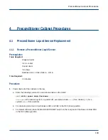
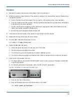
Figure 94. Blower Cabinet PDU Connections
Top cover
screws (25)
Power cable
clamp
Ground stud
Input
terminals
8. Label and disconnect the serial cable, the control cables (6), and the power cables (6) from the top of the
PDU.
9. Remove the 25IP Torx+ screws (4) that attach the PDU to the front frame rails.
10. Remove the 15IP Torx+ screws (4) that attach the support brackets to the rear of the PDU.
11. Slide the PDU out the front of the cabinet. Take care not to damage the serial cable that attaches to the
adjacent cabinet.
3.3.2
Install a Blower Power Distribution Unit (PDU)
Prerequisites
Tools Required:
T15 Torx driver
T25 Torx driver
#2 Phillips screwdriver
1/2-in. socket
Socket driver
Digital multimeter
7/64-in. Allen wrench
3/8-in. socket
Blower Cabinet Procedures
99