
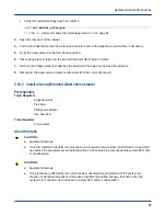


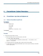


c. For blower cabinets, place the MAIN DISCONNECT switch on the rear panel of the blower cabinet PDU
in the OFF (down) position.
Figure 85. Circuit Breakers for Cabinet (left) and Blower (right)
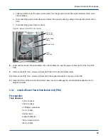
2. Open the front door of the cabinet.
3. Remove the bottom blower from the front and rear of the cabinet.
4. Disconnect the serial cable and the control cables from the blower control assembly and label cables with
missing labels.
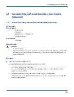
5. Remove the 10IP Torx+ screws (10) that attach the blower control cover to the PDU. Note the orientation of
the blower control assembly to ensure correct installation.
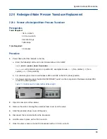
Figure 86. Blower Control Cover
Serial cable
Control cables (6)
Blower control
cover screws (10)
Power cables (6)
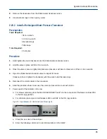
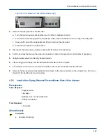
6. Remove the 10IP Torx+ screws (4) that attach the blower control assembly to the PDU and remove the
assembly.
Figure 87. Blower Control Assembly
Blower control
assembly
screws (4)
3.2.2
Install a Blower Control Assembly
Prerequisites
Tools Required:
T10 Torx driver
Time Required:
Blower Cabinet Procedures
95