


Approximately 15 minutes; time varies based on the number of compute cabinets in a row
Procedure
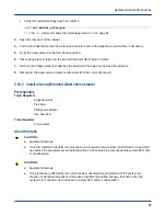
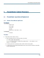
1. Position the blower control assembly on the PDU and reinstall the 10IP Torx+ attachment screws (4).
Figure 88. Blower Control Assembly
Blower control
assembly
screws (4)
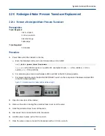
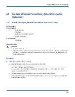
2. Position the blower control cover on the PDU and reinstall the 10IP Torx+ attachment screws (10).
Figure 89. Blower Control Cover
Serial cable
Control cables (6)
Blower control
cover screws (10)
Power cables (6)
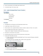
3. Reconnect the serial cable and the six control cables to the blower control assembly.
4. Reinstall the bottom blowers into the front and rear of the cabinet.
5. Close the front door of the cabinet.
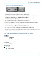
6. Power up all of the cabinets in the row.
a. For blower cabinets, place the MAIN DISCONNECT switch on the rear panel of the blower cabinet PDU
in the ON (up) position.
b. For cabinets, place main circuit breakers CB1 and CB2 in the ON (up) position.
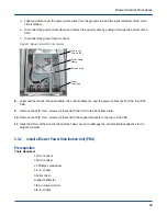
Figure 90. Circuit Breakers for Cabinet (left) and Blower (right)
a. Close the rear door of the cabinet.
b. Enter the following command in a terminal window on the SMW:
smw$
xtcli power up Hostname
Blower Cabinet Procedures
96