


●
Cray requires the power to be disconnected from the PDU when working on components inside the
PDU chassis. If it is necessary to work on components in the PDU with power applied, a minimum 36-
in working clearance must be maintained in front of the PDU. This workspace is required and must be
maintained around all electrical equipment where parts of an energized system may be serviced. To
maintain this clearance, remove the door from the cabinet facing the energized parts, and install an
insulating barier to prevent any grounded equipment from coming in contact with the energized
components in the PDU. Failure to do so could result in serious injury or death.
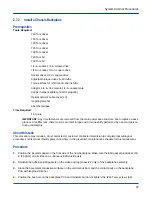
Procedure
1. Power down all of the cabinets in the row.
a. Enter the following command in a terminal window on the SMW:
smw$
xtcli power down Hostname
Hostname
is the cabinet, system, or partition ID; examples include
c0-0
(for a cabinet),
S0
(for a
system), or
p0
(for a partition).
b. For cabinets, place main circuit breakers CB1 and CB2 in the OFF (down) position.
c. For blower cabinets, place the MAIN DISCONNECT switch on the rear panel of the blower cabinet PDU
in the OFF (down) position.
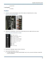
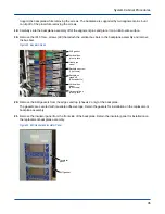
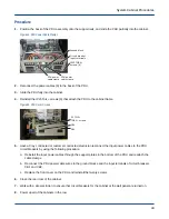
Figure 30. Circuit Breakers for Cabinet (left) and Blower (right)
2. Work with a site electrician to ensure that circuit breakers for the cabinet at the wall panel are off. Use
appropriate lockout/tagout or other site-specific procedures to indicate that the breakers are off.
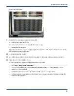
3. Open the rear door of the cabinet.
4. Have a Cray contracted or customer contracted electrician disconnect the input power cables from the PDU
circuit breakers by using the following procedure:
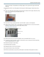
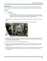
a. Remove the IP15 Torx+ screws (20) that attach the front cover to the PDU and remove the cover.
b. Use the digital multimeter to verify that no voltage is present on the input terminals of circuit breakers CB1
and CB2.
c. Label and disconnect the PDU power cable wires from the ground blocks and the input terminals of circuit
breakers CB1 and CB2.
d. Loosen the power-cable clamps and remove the power cables by pulling them through the bottom of the
PDU.
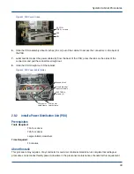
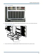
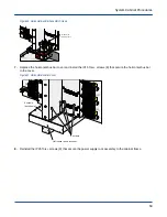
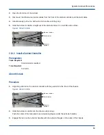
5. Remove the IP25 Torx+ screws (6) that attach the PDU assembly to the cabinet frame.
System Cabinet Procedures
42