


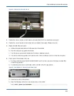


b. Turn the four remaining quarter-turn fasteners with a 5/32-in. balldriver wrench to open the side panel.
c. Grasp both sides of the side panel and lift up to remove the side panel.
d. Place the side panel in a safe location.
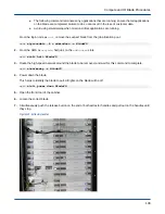
3. Unplug the temperature sensor that needs to be replaced.
Location P10 is the supply sensor and location P11 is the return sensor. Note what pipe the old sensor is
attached to so the new temperature sensor is labeled appropriately.
4.
CAUTION:
●
Personal injury
●
Use caution when cutting the foam with the utility knife. Failure to do so can result in personal
injury.
Cut the foam insulation covering the old temperature sensor with an utility knife and remove it. Use the new
temperature sensor to estimate how much foam to remove. The opening should be approximately 0.5-
to-1.5cm larger than the sensor.
5. Peel off the old temperature sensor from the bare metal piping.
6.
CAUTION:
●
Personal injury
●
Use caution when removing debris with a chisel. Failure to do so can result in personal injury.
Remove any large pieces of foam from the metal piping with a chisel.
7. Remove any remaining debris with sandpaper.
8. Wipe the pipe clean with a clean rag.
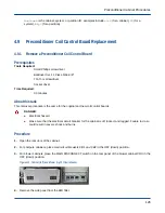
4.6.2
Install a Preconditioner Return or Supply Temperature Sensor
Prerequisites
Tools Required:
Utility knife
Sandpaper
Absorbent rags
Balldriver Set, 11 Piece 5/64-3/8-in.
Time Required:
10 minutes
About this task
This sensor is only used in conjunction with the redesigned cooling components on XC30-LC and XC40-LC
systems.
Preconditioner Cabinet Procedures
119