


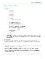


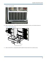


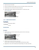


Figure 31. PDU Cover Screws
20 IP15+
TORX+ screws
CB2
CB1
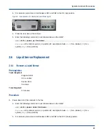
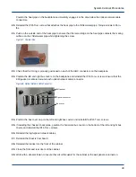
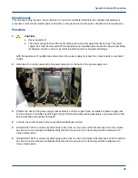
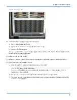
6. Slide the PDU assembly about 6 inches (15 cm) out of the cabinet to access the connectors on the back of
the PDU.
7. Label and disconnect the power cables (6) from the back of the PDU; press the tabs on the sides of the
connectors and pull the connectors straight out.
8. Slide the PDU straight out of the cabinet.
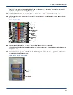
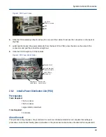
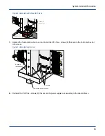
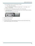
Figure 32. PDU Power Cable Clamps
Ground block
Circuit breaker
input terminals
IP25 TORX+
screws (6)
PDU power
cable clamp
PDU power
cable clamp
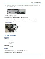
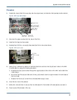
2.8.2
Install a Power Distribution Unit (PDU)
Prerequisites
Tools Required:
T15 Torx driver
T25 Torx driver
Large slotted screwdriver
Time Required:
15 minutes
About this task
This procedure may require a Cray contracted or customer contracted electrician to complete lockout/tagout
procedures or disconnect facility power. Allow time in the preventive maintenance schedule for this requirement.
System Cabinet Procedures
43