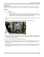


Procedure
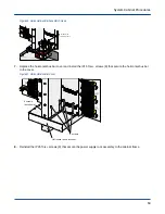
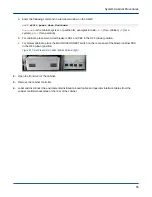
1. Align the guide rail on the chassis host with the guide slot in the front of the chassis.
Figure 57. Chassis Host
2. Slide the chassis host into the chassis until it stops.
Push the center of the face plate to avoid pinching fingers under the extractor handles.
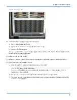
3. Engage the tabs on the extractor handles with the extractor flanges on the sides of the chassis.
4. Simultaneously push in on both extractor handles until they lock in place.
5. Reconnect the Ethernet and serial cables to the front of the chassis host.
6. Close the door to the front cabinet.
7. Power up all of the cabinets in the row.
a. For blower cabinets, place the MAIN DISCONNECT switch on the rear panel of the blower cabinet PDU
in the ON (up) position.
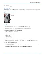
b. For cabinets, place main circuit breakers CB1 and CB2 in the ON (up) position.
Figure 58. Circuit Breakers for Cabinet (left) and Blower (right)
a. Close the rear door of the cabinet.
b. Enter the following command in a terminal window on the SMW:
smw$
xtcli power up Hostname
Hostname
is the cabinet, system, or partition ID; examples include
c0-0
(for a cabinet),
S0
(for a
system), or
p0
(for a partition).
System Cabinet Procedures
63