


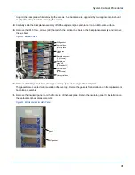


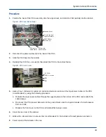


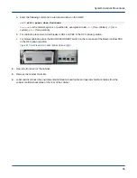

Position the heat pipe on the backplane and carefully engage it in the clips below the optical network cable
connectors.
20. Reinstall the IP25 Torx+ screw that attaches the heat pipe to the chilled-water pipe. Torque screws to 35 in-
lbs.
21. Push on the outside end of the heat pipe to ensure that the raised ridge on the heat pipe contacts the mating
surface on the chilled-water pipe while tightening the screw.
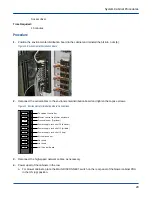
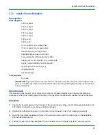
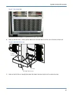
Figure 27. Thermal Pad
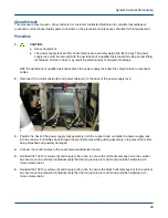
22. Check that the O-ring is properly positioned on each of the AOC connectors on the backplane.
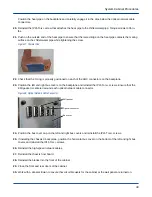
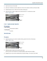
23. Position the left and right bus covers on the backplane and reinstall the IP15 Torx+ screws. Ensure that the
EMI gasket is centered around each optical network cable connector.
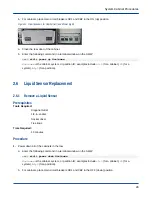
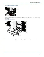
Figure 28. Optical Network Cable Connector
EMI gasket
Optical connector
Bus cover
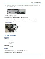
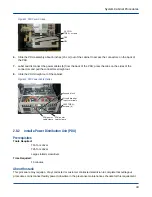
24. Position the bus cover cap on the left and right bus covers and reinstall the IP15 Torx+ screws.
25. If installing the chassis 0 backplane, position the horizontal bus cover on the bottom of the left and right bus
covers and reinstall the IP15 Torx+ screws.
26. Reinstall the high-speed network cables.
27. Reinstall the chassis host board.
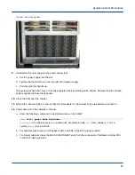
28. Reinstall the blades into the front of the cabinet.
29. Close the front and rear doors of the cabinet.
30. Work with a site electrician to ensure that circuit breakers for the cabinet at the wall panel are turned on.
System Cabinet Procedures
40