4
317961000
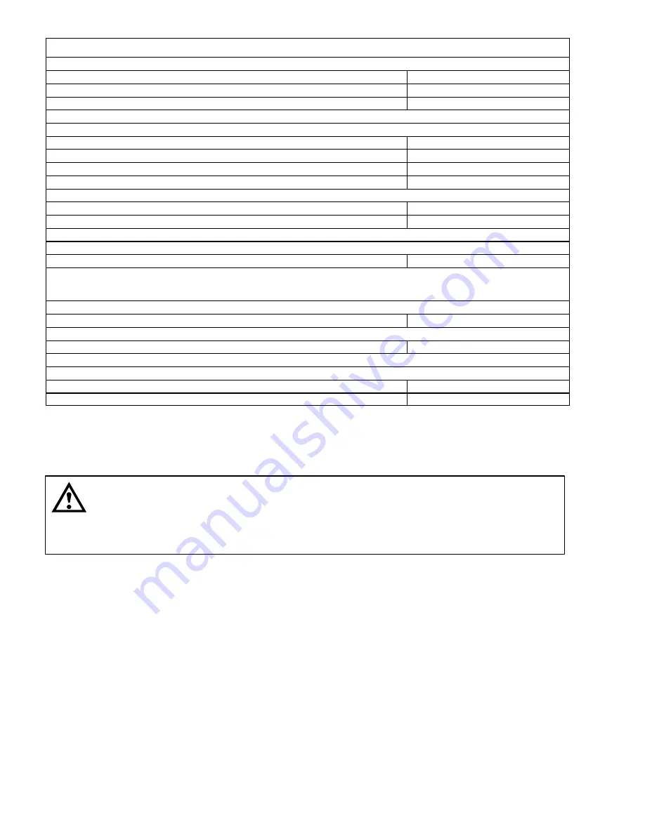
Table 1. Design Data (cont’d)
Overall Dimensions:
Width
13-inches
Height
27-inches
Depth
22-inches
Weights:
Shipping (one carton)
Dry Weight (approximate)
83 pounds
Ice Bank Weight (approximate)
18 pounds
Drop-in Refrigeration Assembly
42 pounds
Water Bath Capacity
7 gallons
(no ice bank)
Dispensing Rate:
Three 12-oz. Drinks/Min. @ 40
°
F or below
(approx)*100
NOTE: *Number of 12-oz. drinks dispensed 40
°
F or below @ 75
°
F syrup and water inlet temperature
and 75
°
F ambient.
Refrigerant Requirement
See Unit Nameplate
Ambient Operating Temperature
40
°
F to 100
°
F
Electrical Requirements:
Operating Voltage
See Unit Nameplate
Current Draw
See Unit Nameplate
THEORY OF OPERATION
(see Figure 2)
WARNING: CO
2
displaces oxygen. Strict attention must be observed in the prevention of
CO
2
(carbon dioxide) gas leaks in the entire CO
2
and soft drink system. If a CO
2
gas leak is
suspected, particularly in a small area, immediately ventilate the contaminated area before
attempting to repair the leak. Personnel exposed to high concentration of CO
2
gas will experience
tremors which are followed rapidly by loss of consciousness and suffocation.
NOTE: The Unit was set up at the factory to dispense a still (non-carbonated) drink from No. 3
dispensing valve and carbonated drinks from remaining valves. No. 3 dispensing valve may be
converted to also dispense a carbonated drink. Refer to TABLE OF CONTENTS for conversion
instructions.
A CO
2
cylinder delivers carbon dioxide (CO
2
) gas through adjustable CO
2
regulators to syrup tanks and to the
remote carbonator. Plain water enters remote carbonator tank and is carbonated by regulated CO
2
pressure
also entering tank. When all dispensing valves except No. 3 are opened, CO
2
pressure exerted upon contents
of syrup tanks pushes syrup from tanks, through Unit syrup cooling coils, to dispensing valves. Carbonated
water is pushed from remote carbonator by CO
2
pressure and is pushed through Unit carbonated water cooling
coils to dispensing valves. Syrup and carbonated water meet simultaneously at dispensing valves resulting in
carbonated drinks being dispensed. A still (non-carbonated) drink is dispensed from No. 3 dispensing valve in
same manner as carbonated drinks except plain water is substituted for carbonated water.
When Unit power cord is plugged into electrical outlet and POWER switch is placed in ‘‘ON’’ position,
compressor, condenser fan motor, and agitator motor will start and begin forming an ice bank in the water tank.
When full ice bank has been formed, compressor and condenser fan motor will stop but agitator motor will
continue to operate circulating ice water in the water tank. Water tank ice bank control will cycle compressor and
condenser fan motors on and off as required to maintain a full ice bank.
Содержание SPIRIT
Страница 6: ......
Страница 7: ...2 317961000 THIS PAGE LEFT BLANK INTENTIONALLY ...
Страница 11: ...6 317961000 THIS PAGE LEFT BLANK INTENTIONALLY ...
Страница 17: ...12 317961000 THIS PAGE LEFT BLANK INTENTIONALLY ...
Страница 21: ...16 317961000 THIS PAGE LEFT BLANK INTENTIONALLY ...
Страница 40: ...35 317961000 THIS PAGE LEFT BLANK INTENTIONALLY ...


