OPERATING & INSTALLATION INSTRUCTION 2-POST-LIFT
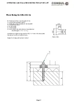
one 100 mm from the outer edge of the sheet metal). Lay the drilling template on the floor and let in 2
plugs (100 mm diameter). Finally screw the chain cover to the floor using 2 wood screws (8 mm diameter).
There is an additional sheet enclosed for the chain cover of the H264/H265 lift with symmetrical bearing
arms. If necessary, screw this in the same way as described above.
When installing the electrical cables be careful not to mix up the wires!
Before commencing the electrical work, the instructions for initial installation (following pages) should be
read and observed!
If any further questions arise, Consul service is at your disposal.
The electrical installation of the lift must be carried out by an electrical engineer according to the enclosed
circuit diagram and IEE Regulation 0100. The lift should operate in accordance with the travel direction
symbols when the main drive switch is activated. If necessary change the direction of turn by swaping
around the 2 relevant leads.
Attention: If turned in the wrong direction, on no account should you continue to the end position as the lift
will get stuck.
Lower the carriages, pull out the short angled ends of the arm-lock so that about 40 mm remains on the
other side. Grease the carriage pivot points well. Turn the angled end of the lower arm-lock upwards. Fit the
lifting arms, insert the lwoer arm lock into the arm at the same time. The angled end of the upper arm-lock
must be turned with the aid of pliers into the relevant holes after the swing arms have been fitted. Secure the
lifting arms with the spezial bolts provided.
With the lift H264-C with sill lifting chassis, the chassis is connected and secured against slipping off the
take-up bolts with hexagonal M10 screws. The locking device of the lifting carriage can be removed if
necessary.
The buffer points are installed and secured using the enclosed springs.
Caution:
Protective conductor checks must be carried out following initial installation, after repairs, after
alterations to the installation, as well as prescribed under the VDE regulation 0100!
See drawing
After installing the lift be careful to ensure the correct alignment of the switch wire in the main column. The
switch plates must be located between the back wall of the column and the backing plate.
Check the spindle cover. The fixing brackets for the tension band must be sufficiently spaced from the pillars
so that the tension band does not catch and get damaged. The fixing brackets may need some folow up
adjustment.
If the tigehtening strap creates any summing sounds during operation, lubricate the back of the strap with
some grease.
Test the end cut-out switch top and bottom with a trial run. When the lift has been lubricated according to the
lubrication shedule on the main column and its operation checked by a qualified engineer in accordance with
BGG945, then commissioning can follow.The result of the test must be recorded in the test book!
Page 37
Содержание 2.25 EMC
Страница 66: ...OPERATING INSTALLATION INSTRUCTION 2 POST LIFT Electric diagram for chain lifts H264 H265 Page 66 ...
Страница 67: ...OPERATING INSTALLATION INSTRUCTION 2 POST LIFT Electric diagram H342 Page 67 ...
Страница 68: ...OPERATING INSTALLATION INSTRUCTION 2 POST LIFT Electric diagram H325 Page 68 ...
Страница 69: ...OPERATING INSTALLATION INSTRUCTION 2 POST LIFT Electric diagram with rotary reversing switch Page 69 ...
Страница 70: ...OPERATING INSTALLATION INSTRUCTION 2 POST LIFT Electric diagram with push button Page 70 ...
Страница 71: ...OPERATING INSTALLATION INSTRUCTION 2 POST LIFT Page 71 ...
Страница 72: ...OPERATING INSTALLATION INSTRUCTION 2 POST LIFT Page 72 ...
Страница 73: ...OPERATING INSTALLATION INSTRUCTION 2 POST LIFT Page 73 ...
Страница 74: ...OPERATING INSTALLATION INSTRUCTION 2 POST LIFT Page 74 ...
Страница 75: ...OPERATING INSTALLATION INSTRUCTION 2 POST LIFT Page 75 ...
Страница 76: ...OPERATING INSTALLATION INSTRUCTION 2 POST LIFT Page 76 ...
Страница 77: ...OPERATING INSTALLATION INSTRUCTION 2 POST LIFT Page 77 ...
Страница 78: ...OPERATING INSTALLATION INSTRUCTION 2 POST LIFT Page 78 ...
Страница 79: ...OPERATING INSTALLATION INSTRUCTION 2 POST LIFT Page 79 ...
Страница 80: ...OPERATING INSTALLATION INSTRUCTION 2 POST LIFT Page 80 ...

