background image

OPERATING & INSTALLATION INSTRUCTION 2-POST-LIFT


Practical use with the post-lifts 

 
Switch the main switch to the " Ein " (on) position. Turn the control knob to move the lift in the direction 
indicated by the arrows. On release of the  control knob it returns automatically to the “off” position.  
 
Operating the lift is only permitted by authorised persons! 
 
According to the regulations for prevention of accidents, persons under the age of 18 are not permitted to 
operate the lift without supervision.  
 
The lift is designed only as a vehicle lift, it should not be used for other purposes.  
See instruction on the lift column. 
 
If there are any faults with the lift, turn off electricity, make safe, secure against unauthorised use and 
contact the Consul Service Section.  
 
See the operation label on the lift column! 
 
Before lifting or lowering a vehicle check that nobody is in danger, that nothing is leaning against the vehicle 
and no obstacles are underneath it. 
 

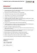
Attention:


With some vehicles, higehr lifting apparatus is necessaryy. As an necessary, a set (4) spacing bushes is 
available. This ensures safe lifting of the vehicle. 
 
When using a drive-on chassis, the chassis must be fully lowered before driving on to the lift. 
The total vehicle weight may not exceed the authorised  capacity and load dispatching.  
 
Only original accessories may be used as load supporting devices (type tested parts), wooden blocks or 
other devices for load lifting are not permitted. It is advidable that the vehicle should be driven on so that the 
centre of gravity is between the lift columns (especially with the asymmtric swivel arms). 


In order to guarantee a safe lift of the vehicle it may only be lifted at all 4 lifting points 
as laid down by the manufacturer. 
Check the safety of the lifting after having set up a little the vehicle. 

Pay attention to the centre of gravity when working with heavy parts as it can cause the vehicle being raised 
to fall. Only use the lift as intended: for lifting vehicles. Other, apparently practical uses are not among ist 
intended purposes. 
 
It is forbidden to use the lifts to raise heavy vehicle pars, eg, engines. The swivel arms are fitted with 
blocking devices which work automatically. These stop the swivela rms moving after a short lifting distance 
(on lifts with a lifting capacity of 4 to and 15 mm on lifts with a 6 to capacity) and release them again when 
lowered through 15 mm. 
 
If the arms have to be swung to a greater height, eg, in order to place a vehicle on a bench, then a hand bolt 
can be installer. 


Page 8

Содержание 2.25 EMC

Страница 1: ...sul 2 35 EL H301 Consul 2 40 EL H327 Consul 2 60 H342 Consul 2 60 EL H331 Consul 2 25 RMC H339 Prolift 3003 GA H325 Prolift 2 30 EL H354 Prolift 2 40 EL H355 Version 1 0 Stand Juli 2004 Consul Werkstattausrüstung GmbH Daimlerstraße 1 58553 Halver Tel 02353 7009 0 Telefax 02353 12515 E mail info consul gmbh de ...

Страница 2: ...lift H264 H265 H325 36 Chain break switch H264 H265 H325 38 Installation and Commissioning of chainlift H342 39 Switch again chain break H342 41 Load nut failure 43 Load bearing nut testing 44 Description of the main board SGMX2 45 Faults and Causes 50 Emergency lowering II 51 Emergency lowering I 52 Maintenance and Service 53 Automatic lubrication system 54 Manual arm lock override 56 Manual arm ...

Страница 3: ...25 RMC H339 38308 3 2 Post Lift Prolift 3003 GA H325 37862 0 2 Post Lift Prolift 2 30 EL H354 39281 1 2 Post Lift Prolift 2 40 EL H355 39282 9 In the event of any alteration to the machine not agreed with us the present declaration shall lose its validity Relevant EC guidelines EC machine guidelinee 98 37 EG dated 22 07 98 Electron magnetic compatibility 89 336 EWG in the version 91 263 EWG in the...

Страница 4: ...h the statical calculations engineer Lifts can be anchored with dowels shear connectors or with M12 through bolts or threaded rods minimum strength 8 8 and washers see also BGG 945 5 Performances of our customer service section The Consul service section or Consul authorised partner takes on the setting up of the lift with the following performances Dowelling to the floor Assembly of the lift For ...

Страница 5: ...rsons working on them we draw your attention to the fact that we must tie the guarantee entitlement of the operator to the correctly performed safety acceptance and entry of this in the check list Always uses original spare parts The use of any other parts invalidates the design permit and all claims under warranty Service memorandum standard fundaments Individual fundaments Concrete floor hall fl...

Страница 6: ... large amount of work is carried out with solvent containing materials pay attention to the risk of explosion In its standard form the drive is not protected against explosion Safety devices Your lift is equiped with several safety devices to ensure workers safety if the list is used according to this manual Please take care of this safety devices when installing the lift and check them after any ...

Страница 7: ...utomatic lubrication system with original Consul Spindle Oil 9 The lift is preprogrammed in the factory and must be adjusted to local conditions Check that the foot protection facility is at the correct height compulsory stop and signal tone 10 Be aware of the alignment outward lean of the columns 11 Check the gap between the steering frame and the tension band correst and grease the back of the t...

Страница 8: ...be fully lowered before driving on to the lift The total vehicle weight may not exceed the authorised capacity and load dispatching Only original accessories may be used as load supporting devices type tested parts wooden blocks or other devices for load lifting are not permitted It is advidable that the vehicle should be driven on so that the centre of gravity is between the lift columns especial...

Страница 9: ...ions therein Eg Part 2 Point 5 Nature extent and execution of tests Appendix 2 Instruction on the main page in the test book BGG 945 1 testing of lifts The quoted paragraphs are extracts otherwise BGG945 is binding The required tests are carried out by Consul Construction Services according to the regulations Please ask Consul Partners for thier reasonably priced maintenance contracts Page 9 ...

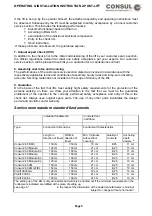
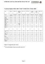
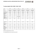
Страница 10: ...0 2560 2920 Max vehicle width mm 2 460 2 260 2 460 2 460 2 560 2260 2700 2380 2730 stroke mm 1 900 1 900 1 900 1 900 1 900 1900 1900 1750 Lifting height mm 1995 1990 1980 2005 2005 1990 1995 1905 min arm clearance mm 95 90 Drive on Heigh 70 95 85 70 85 115 Lifting time sec 47 47 47 47 47 47 47 40 Net weight kg 620 620 650 700 700 620 700 1000 Load capacity kg 3 000 3 000 3 000 3 500 4000 3000 4000...

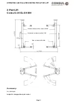
Страница 11: ...STRUCTION 2 POST LIFT 2 Post Lift Consul 2 30 EL S H300 Distance between the columns 2800 Dimension outside coulmns 3100 Stroke 1900 Max vehicle width 2460 Accessory See catalogue Subject to change without prior notice Page 11 ...

Страница 12: ... Lift Consul 2 30 EL A H300 H354 2 Post Lift 2 30 Modula with asymmetric swivel arms Dimension outside columns 2900 Distance between the columns 2600 Stroke 1900 Max vehicle width 2260 Accessory See catalogue Subject to change without prior notice Page 12 ...

Страница 13: ...ost Lift Consul 2 30 EL C H300 2 Post Lift 2 30 Modula with sill lifting chassis Dimension outside coulmns 3100 Distance between the columns 2800 Stroke 1900 Max vehicle width 2460 Accessory See catalogue Subject to change without prior notice Page 13 ...

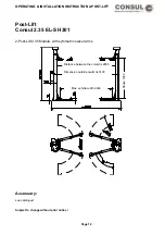
Страница 14: ...st Lift Consul 2 35 EL S H301 2 Post Lift 2 35 Modula with symmetric swivel arms Distance between the columns 2800 Dimension outside coulmns 3100 Stroke 1900 Max vehicle width 2460 Accessory see catalogue Subject to change without prior notice Page 14 ...

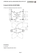
Страница 15: ...ul 2 40 EL S H327 H355 2 Post Lift 2 40 Modula with symmetric swivel arms Dimension outside coulmns 3100 Max vehicle width 2460 Distance between the columns 2700 Max 2025 Stroke 1900 Accessory See catalogue Subject to change without prior notice Page 15 ...

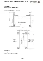
Страница 16: ...ul 2 25 RMC H339 2 Post Lift 2 25 RMC Modula with frame Distance between the columns 2800 Dimension outside coulmns 3100 Strke 1900 Max vehicle width 2460 ramp Safety bar Platform lenght 2400 Accessory see catalogue Subject to change without prior notice Page 16 ...

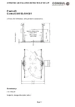
Страница 17: ...IFT Post Lift Consul 2 60 EL S H331 2 Post Lift 2 60 Modula with symmetric swevel arms Base frame height Stroke 1750 Distance between the columns 2770 Max vehicle width 2380 Accessory see catalogue Subject to change without prior notice Page 17 ...

Страница 18: ...width mm 2440 2440 2440 2 460 2380 2350 Stroke mm 1 900 1 900 1 900 1 900 1750 1900 Lifting height mm 2000 1985 2000 2005 1925 1990 min arm clearance mm 98 85 Drive on high 80 95 115 90 Lifting time sec 47 47 47 47 45 45 Net weight kg 620 620 650 700 700 650 Load capacity kg 3 000 3 000 3 000 3 500 6000 3000 Motor power kW 3 3 3 3 3 3 Voltage V 400 400 400 400 400 400 ED power S3 S3 S3 S3 S3 S3 Cu...

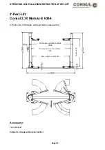
Страница 19: ...t Lift Consul 2 30 Modula S H264 2 Post Lift 2 30 Modula with symmetric swivel arms Distance between the columns 2780 Dimension outside coulmns 3080 Stroke 1900 Max vehicle width 2440 Accessory see catalogue Subject to change without prior notice Page 19 ...

Страница 20: ...Lift Consul 2 30 Modula AS H264 2 Post Lift 2 30 Modula witht asymmetric swivel arms Distance between the columns 2430 Dimension outside coulmns 2730 Stroke 1900 Max vehicle width 2090 Accessory see catalogue Subject to change without prior notice Page 20 ...

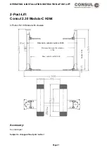
Страница 21: ...T 2 Post Lift Consul 2 30 Modula C H264 2 Post Lift 2 30 Modul with chassis Max vehicle width 2440 Distance between the columns 2780 Dimension outside coulmns 3080 Stroke 1900 Accessory See catalogue Subject to change without prior notice Page 21 ...

Страница 22: ... POST LIFT 2 Post Lift Consul 2 35 Modula S H265 2 Post Lift 2 35 Modul with symmetric swivel arms Max vehicle width 2440 Distance between the columns 2780 Stroke 1900 Accessory See catalogue Subject to change without prior notice Page 22 ...

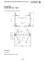
Страница 23: ...CTION 2 POST LIFT 2 Post Lift Prolift 3003 GA H325 2 Post Lift with asymmetric swivel arms Strike 1900 Distance between the columns 2610 Max vehicle width 2350 Accessory see catalogue Subject to change without prior notice Page 23 ...

Страница 24: ...e same time a mechanical blocking system is engaged which prevents continued movement to the lowered position in the event of worn threads In this way unintentional travel on the safety nuts is avoided The swivel arm lock of the 6 to lift stops the load arms moving after travelling upwards approx 15 mm from the lowered position This is to prevent the lifting apparatus slipping from the jacking poi...

Страница 25: ...he power in the event of a broken chain thus preventing the load being raised from falling off due to misalignment Regular operating checks The heat sensor in the drive motors stops the lift in the event of overheating and only allows the lift to restart after a cooling down period The 2 Post Lift 265 capacity 3500 kg is made with symmetrical swivel bearing arms as standard Other lifting apparatus...

Страница 26: ... be made about the corresponding fixing system The depths of the anchorage of the shear connectors dowel anchors are not supplied have to be followed see instructions of the dowel manufacturers Ohterwise there is no sufficient security for the persons working under the post lift The correct length L of the active part of the anchor bolt is obtained by adding the measurements h thickness of the flo...

Страница 27: ...t depth by B25 s thickness of floor material til concrete B25 t foot plate thickness g screw length L dowel length X according to the instructions of manufacturer dowel length L h s t g Accordance to type anchor used for the 21 1 hole in the base plate the washer must be of sufficient size Subject to change without prior notice Page 27 ...

Страница 28: ...57 cm m under reinforcement BST 500 M permissible aSx y 3 77 cm m above reinforcementBST 500M Column fitting H300 H301 for ex Liebig adhesive anchors Type 12 for Hilti HVA HAS M12x110 H327 for ex Liebig adhesive anchors Type 16 or Hilti HVA HAS M16x125 Important Always follow the assembly instructions and keep to the min anchoring depths specified by the dowel manufacturers Individual certificats ...

Страница 29: ... thickness of floor material til concrete B25 t foot plate thickness g screw length L dowel length X according to the instructions of manufacturer dowel length L h s t g UPAT UKA 3 M16 Hilti HSL TZ M16 Fischer M16 Accordance to type anchor used for the 26 1 hole in the base plate the washer must be of sufficient size Subject to change without prior notice Page 29 ...

Страница 30: ...nforcement BST 500 M permissible aSx y 3 77 cm m above reinforcementBST 500M Column fitting for ex Heavy anchor HSL TZ M16 or UPAT UKA 3 M16 Important Always follow the assembly instructions and keep to the min anchoring depths specified by the dowel manufacturers Individual certificats must be provided for anchroing on an exixting reinforced concrete ceiling Tests on existing concrete floor are n...

Страница 31: ...bolt depth by B25 s thickness of floor material til concrete B25 t foot plate thickness g screw length L dowel length X according to the instructions of manufacturer dowel length L h s t g Accordance to type anchor used for the 21 1 hole in the base plate the washer must be of sufficient size Subject to change without prior notice Page 31 ...

Страница 32: ... asx 2 57 cm m under reinforcement BST 500 M permissible aSx y 3 77 cm m above reinforcement BST 500M Column fitting for ex Liebig adhesive anchors Type 12 for Hilti HVA HAS M12x110 Important Always follow the assembly instructions and keep to the min anchoring depths specified by the dowel manufacturers Individual certificats must be provided for anchoring on an exixting reinforced concrete ceili...

Страница 33: ...r fixing H342 Attention Base frame height 60 mm Base frame must be placed on the total surface Base frame in a horizontal position frame Anchors HSL G TZ M12 50 according to the instructions of manufacturer Subject to change without prior notice Page 33 ...

Страница 34: ... main column by means of a hollow pipe provided on site An overhead conduit can also be provided through which the cables can be fed When installing the cables it is important to ensure that the wires are not mixed up Before commencing the electrical work carefully read and observe the instructions regarding initial installation follwing pages Consul Service is available should there be further qu...

Страница 35: ...be sufficiently spaced from the column so that the tension band does not catch and get damaged The fixing brackets may need some follow up adjustment The spindles must be oiled and the spindle oilers on the lifting carriage are to be filled with Consul Spindle Oil using the observation holes on the columns order no 24960 3 Should there be a buzzing noise from the tension bands when the lift is in ...

Страница 36: ...t To bolt down the base plates 10 M16 heavy duty anchors are necessary eg Hilti HSL G TZ or similar anchors from another manufacturer The drilling depth in the concrete BN25 must eg Hilti HSL G TZ be to a minimum depth of 125 mm The depth of the anchor bolt must be no less than 100 mm The plugs must have a minimum resistance strength of 9 kN The torque value is 120 Nm The length of the plugs to be...

Страница 37: ...er arm lock into the arm at the same time The angled end of the upper arm lock must be turned with the aid of pliers into the relevant holes after the swing arms have been fitted Secure the lifting arms with the spezial bolts provided With the lift H264 C with sill lifting chassis the chassis is connected and secured against slipping off the take up bolts with hexagonal M10 screws The locking devi...

Страница 38: ... for the limit switch E confirm shaft F column column base plate G compression spring H connection element I safety ring J woodruff key K limit switch complete L bearing M chain wheel After trial runs with a nominal load the chain break switch should be checked for trouble free operation and readjusted if necessary Page 38 ...

Страница 39: ...e snagged or damaged The main column is put in place as described before The end of the cable is pulled tight and then pulled from below throught the column base plate and the conduit inside it The cable for the chain break switch is installed in the same conduit in advance Set up the slave column pull lossely secured cables and run them through the back wall of the column to the control box Move ...

Страница 40: ...matically the spindles of the lift Control regularly the level of the oil that can be seen from outside and if necessary refill see Maintenance and care and the sheet on the lift Should there be a buzzing noise from the tension bands when the lift is in drive then multi purpose grease can be applied th the back of the cover Test the end cut out switch top and bottom with a trial run If necessary r...

Страница 41: ...OPERATING INSTALLATION INSTRUCTION 2 POST LIFT Switch again chain break H342 1 twist joint 2 limit switch 3 fillister head 4 switch lever 5 Seeger annular gear 6 compression spring 7 slider Page 41 ...

Страница 42: ...g elements the lift can only be lowered If the carriage is moved upwards again the safety lock catches on the bar on the back wall of the lift and stops the lift rising The locking mechanism must under no circumstances be disconnected If the lift stops about 10 mm above the ground level the supporting elements are defect According to the safety lock device the lift has to be out of function before...

Страница 43: ...OPERATING INSTALLATION INSTRUCTION 2 POST LIFT Load failure nut Roller bearing Load nut Carriage Bar Safety Lock Safey nut Fig 2 Load nut o k Fig 3 Load nut destroyed Page 43 ...

Страница 44: ...OPERATING INSTALLATION INSTRUCTION 2 POST LIFT Load bearing nut testing Check gap 1 mm Load nut Lifting arm locator should be greased every 3 months Testing nut 354167 Page 44 ...

Страница 45: ...een the lowest point of the arm and the ground there should be at least 10 mm of space The upper limit Between the base plate and the lowest point of ther arm there should be A max difference of 1900 mm Safety stop There should be a minimum of 200 mm between the lowest point of the arm and the ground Preparation for the initial installation During the initial installation of the arms or after repa...

Страница 46: ...test mode both red and green LED s blink To ovecame this situation change defective parts or run test mode again Programming Initial installation of the potentiometer already done Step Switch position Enter button Function A 4 push operate mode master column only lower the carriage til approx 10 mm over the ground and 10 mm overrun reserve B 5 push operate mode slave column only as step A C 1 push...

Страница 47: ...g or put it away until end of this process 5 Main switch off 6 Main switch on 7 The control is actived by turning the code switch to 8 and pushing the Enter button Test connections signal and EEPROM Saving Carriages are not near the end stops 1 Turn switch to code 8 2 Push ENTER button 3 LED 2 is blinking green the signal is on 4 Turn the up switch until the carriages start to move up 5 The lift w...

Страница 48: ...d a fault acccurs during test mode both red and green LED s blink To overcame this situation change defective parts or run test mode again New driving mode Switch on the main board programming initial installation of the potentiometer already done Step Switch Enter button Fonction A 4 push Oparate mode Lower the carriage til approx 10mm over the ground and 10 mm overrun reserve B 5 Not active C 1 ...

Страница 49: ...ontrol is actived by turning the code switch to 8 and pushing the Enter button Test connections signal and EEPROM Saving Carriages are not near the end stops I Turn switch to code 8 II Push ENTER button III LED 2 is blinking green the signal is on IV Turn the up switch until the carriages start to move up V The lift will move a short distance upwards VI LED 1 is blinking green the signal is on VII...

Страница 50: ...s to the electric motor to see whether current is being supplied in all 3 phases Check the safety contacts and the drive belts Carriage only rises approx 100 mm Remedy Check safety devices load bearing nut is probably worn and the safety lock is actived shut down the lift secure against unauthorised use and inform Consul Service Section Arm lock does not work Remedy Check locking blocks check spri...

Страница 51: ...arge pulley The main switch must be on the off position The screws should be inserted into the two contactors and locked into position as shown in the diagram to enable emergency lowering If the two sides are not synchronised then by locking only one contactor the arms can be brought on the same level Extreme care must be taken and levelling should be done in small steps Locking the contactors the...

Страница 52: ...t disc The main switch must be set to 0 As per the sketch the lowering contactors must be locked for a single emergency lowering process by using the enclosed plastic screws If there is any uneveness in the lifting apparatus it may be possible to overcome this by locking just one of the safety devices Be especially careful while carrying out all movements which should only take place for short int...

Страница 53: ...break downs can occur which are not occur which are not covered by the guarantee In this case any costs airsing may have to be borne by the customer The swivel arm joints must be greased when necessary and at least quarter yearly oil underneath the safety screws Where lifts are exposed to the weather the lubrication programm should be doubled see the lubrication instructions on the main column The...

Страница 54: ...end lubrication SAE 20 The flat wick should be secured about 20 25 mm over the oil container with a safety needle and fitted pointing downwards Please check during assembly 4 Clamp the oil container to the carriage Repeat this procedure on the column Then check the correct position of the oil container again 5 Now replace the cover plates and connect the lift to the mains agains Check the oil at r...

Страница 55: ...the nut The lift has an adjustable brake on both columns This stops the weight of the vehicle causing the columns to lower at different speeds The tension on the springs can be adjusted to synchronise the lifting carriages Subject to change without prior notice When the hood has been removed and the system is load free it should just be possible using both hands to turn the large belt disc Page 55...

Страница 56: ...indle Put the lever through the front of the hole of the carriage Please check the lever The U profile have to set down on the first threat bar Screw the lever on the guide bar 2x Screw the guide bar in the threated bore of the lever 7 mm deep 2x Screw the arm lock override of its function Fasten the cover tape with the metal stripe and the nuts again Subject to change without prior notice Page 56...

Страница 57: ... INSTALLATION INSTRUCTION 2 POST LIFT Manual arm lock override for 6 to lifts Identification nr 39766 1 6855 1 ball handle 667 6 threaded stud 37374 6 plunger block Subject to change without prior notice Page 57 ...

Страница 58: ...OPERATING INSTALLATION INSTRUCTION 2 POST LIFT Lifting plate with pin bushin 2 Notches Stroke block Lifting plate bush Page 58 ...

Страница 59: ...OPERATING INSTALLATION INSTRUCTION 2 POST LIFT Lifting plate lift 6 to Pull outwards and lift into position 269407 safety spring Page 59 ...

Страница 60: ...OPERATING INSTALLATION INSTRUCTION 2 POST LIFT Control unit with rotary reversing switch 36953 8 for H300 H301 H354 H355 Page 60 ...

Страница 61: ...cription 1 366553 operating switch 2 369546 main switch 3 361576 audible alarm device 4 356154 circuit board 9 370528 conduction band with plug 11 370536 box complete 13 369561 handle knob with adapter 19 318964 main contactor 23 316026 european socket 28 360115 fuse socket 29 318972 fuse 30 318980 fuse 11 2000 Subject to change without prior notice Page 61 ...

Страница 62: ...OPERATING INSTALLATION INSTRUCTION 2 POST LIFT Control unit with push buttons 38032 9 Subject to change without prior notice Page 62 ...

Страница 63: ...on A 380337 double switch B 361576 audible alarm device C 356154 circuit board D 370528 conduction band with plug E 395970 box complete F 318964 main contactor G 316026 european socket H 360115 fuse socket I 318972 fuse J 318980 fuse K 369546 main switch 10 2002 Subject to change without prior notice Page 63 ...

Страница 64: ...OPERATING INSTALLATION INSTRUCTION 2 POST LIFT OPERATING INSTALLATION INSTRUCTION 2 POST LIFT Page 64 Control unit H325 Prolift 3003 GA Page 64 ...

Страница 65: ...nt Nr description 1 366553 operating switch 3 361576 audible alarm device 4 356154 circuit board 9 370528 conduction band with plug 11 370536 box complete 13 369561 handle knob with adapter 19 318964 main contactor 28 360115 fuse socket 29 318972 fuse 03 2002 Subject to change without prior notice Page 65 ...

Страница 66: ...OPERATING INSTALLATION INSTRUCTION 2 POST LIFT Electric diagram for chain lifts H264 H265 Page 66 ...

Страница 67: ...OPERATING INSTALLATION INSTRUCTION 2 POST LIFT Electric diagram H342 Page 67 ...

Страница 68: ...OPERATING INSTALLATION INSTRUCTION 2 POST LIFT Electric diagram H325 Page 68 ...

Страница 69: ...OPERATING INSTALLATION INSTRUCTION 2 POST LIFT Electric diagram with rotary reversing switch Page 69 ...

Страница 70: ...OPERATING INSTALLATION INSTRUCTION 2 POST LIFT Electric diagram with push button Page 70 ...

Страница 71: ...OPERATING INSTALLATION INSTRUCTION 2 POST LIFT Page 71 ...

Страница 72: ...OPERATING INSTALLATION INSTRUCTION 2 POST LIFT Page 72 ...

Страница 73: ...OPERATING INSTALLATION INSTRUCTION 2 POST LIFT Page 73 ...

Страница 74: ...OPERATING INSTALLATION INSTRUCTION 2 POST LIFT Page 74 ...

Страница 75: ...OPERATING INSTALLATION INSTRUCTION 2 POST LIFT Page 75 ...

Страница 76: ...OPERATING INSTALLATION INSTRUCTION 2 POST LIFT Page 76 ...

Страница 77: ...OPERATING INSTALLATION INSTRUCTION 2 POST LIFT Page 77 ...

Страница 78: ...OPERATING INSTALLATION INSTRUCTION 2 POST LIFT Page 78 ...

Страница 79: ...OPERATING INSTALLATION INSTRUCTION 2 POST LIFT Page 79 ...

Страница 80: ...OPERATING INSTALLATION INSTRUCTION 2 POST LIFT Page 80 ...

Отзывы: