


OPERATING & INSTALLATION INSTRUCTION 2-POST-LIFT
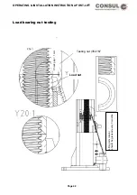
Emergency lowering II
Important:
While in the emergency lowering procedure. The automatic end limits are switched off. It is possible to drive the lift into
the floor causing damage.
Notes:
The procedure described below for the emergency lowering of the lift may only be undertaken by authorised, trained
personnel. A second person should watch the procedure from outside the operating area to ensure the safety of the
operator and vehicle.
The emergency lowering procedure must be terminated immediately, if any danger should arise. Restarting the
emergency lowering procedure should begin again once the cause of the danger has been removed. It is only possible to
lower the lift once, making sure that the bad carrying parts do not touch the floor.
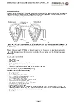
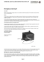
Operating the emergency lowering procedure:
Emergency lowering using the motors can be necessary if the electronic controls fail. If other elements fail, then the lift
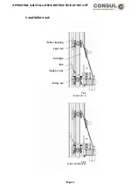
should be lowered manually (by turning the bolt on the large pulley).
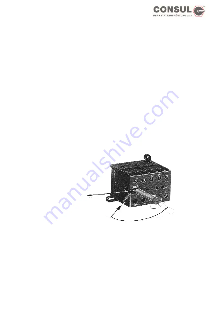
The main switch must be on the „off“ position. The screws should be inserted into the two contactors and locked into
position (as shown in the diagram) to enable emergency lowering.
If the two sides are not synchronised then by locking only one contactor, the arms can be brought on the same level.
Extreme care must be taken and levelling should be done in small steps.
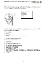
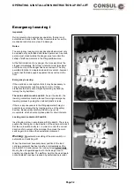
Locking the contactors
(the second contactor is
the Mirror image):
Direction for pushing the
operating bar
plastic screw
Insert the locking screw at an angle as shown in the sketch. Using the screw, press the locking bar slighly in the direction
of the arrow, then turn the srew clockwise, locks the locking bar. Set the main switch to 1. The emergency lowering
procedure can be carried out by loosely inserting the switch toggle after removing it from the lid.
Warning: No automatic end switching-off.
When the maximum necessary lower position of the load carrying equipment has ben reached, immediately
set the main switch to 0 and remove the locking immediately. Moving the unit upwards again with the locking
screw in position is not permitted. The lift must not be used again until all defects have been repaired by
authorised personnel
.
Page 51
Содержание 2.25 EMC
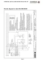
Страница 66: ...OPERATING INSTALLATION INSTRUCTION 2 POST LIFT Electric diagram for chain lifts H264 H265 Page 66 ...
Страница 67: ...OPERATING INSTALLATION INSTRUCTION 2 POST LIFT Electric diagram H342 Page 67 ...
Страница 68: ...OPERATING INSTALLATION INSTRUCTION 2 POST LIFT Electric diagram H325 Page 68 ...
Страница 69: ...OPERATING INSTALLATION INSTRUCTION 2 POST LIFT Electric diagram with rotary reversing switch Page 69 ...
Страница 70: ...OPERATING INSTALLATION INSTRUCTION 2 POST LIFT Electric diagram with push button Page 70 ...
Страница 71: ...OPERATING INSTALLATION INSTRUCTION 2 POST LIFT Page 71 ...
Страница 72: ...OPERATING INSTALLATION INSTRUCTION 2 POST LIFT Page 72 ...
Страница 73: ...OPERATING INSTALLATION INSTRUCTION 2 POST LIFT Page 73 ...
Страница 74: ...OPERATING INSTALLATION INSTRUCTION 2 POST LIFT Page 74 ...
Страница 75: ...OPERATING INSTALLATION INSTRUCTION 2 POST LIFT Page 75 ...
Страница 76: ...OPERATING INSTALLATION INSTRUCTION 2 POST LIFT Page 76 ...
Страница 77: ...OPERATING INSTALLATION INSTRUCTION 2 POST LIFT Page 77 ...
Страница 78: ...OPERATING INSTALLATION INSTRUCTION 2 POST LIFT Page 78 ...
Страница 79: ...OPERATING INSTALLATION INSTRUCTION 2 POST LIFT Page 79 ...
Страница 80: ...OPERATING INSTALLATION INSTRUCTION 2 POST LIFT Page 80 ...