OPERATING & INSTALLATION INSTRUCTION 2-POST-LIFT
Attention:
The self-securing screws only reach complete turning security after 24 hours..
As a first step when assembling, check that the cables which have been laid are undamaged and correctly
located. The cables of the slave column and the chain break switch should show no slackness in the region
of the switch box conduit or loop slackly into the columns. They should rug closely together.
Establish the electrical connection. The electrical installation of the lift must be performed by an electrical
expert on the basis of the connection diagram provide and of the VDE regualtion 0100. Operate the
operating switch, the lift must move in accordance with the direction of travel symbols, if necessary alter the
direction of rotation by interchanging two conductors.
Caution!
Protective conductor checks must be carried out following initial installation, after repairs, after
alterations to the installation, as well as as prescribed under the VDE regulation 0100!
Check the spindle cover. The fixing brackets for the tension band must be sufficently spaced from the
columns so that the tension band does not catch and get damaged. The fixing brackets may need some
follow-up adjustment.
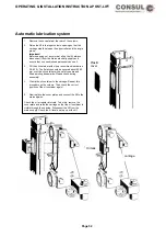
The spindle must be oiled and the spindle oilers on the lifting carriage are to be filled with Consul Spindle Oil
using the obser (order no: 29460.3). Lifts with eletrooilers grease automatically the spindles of the lift.
Control regularly the level of the oil that can be seen from outside and if necessary refill (see Maintenance
and care and the sheet on the lift).
Should there be a buzzing noise from the tension bands when the lift is in drive then multi-purpose grease
can be applied th the back of the cover.
Test the end cut-out switch top and bottom with a trial run. If necessary readjust the locking pins of the
swivel arms. In the lower position, the locking pins can be only max. 3-5 mm over the rotary segment. When
the lift has been lubricated according to the lubrication schedule on the main column and its operation
checked by a qualified engineer in accordande with BGG945, then commissioning can follow.
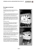
Test the chain break switch (see drawing ) is operating before fixing the base frame cover. To do this push
the chain sideways with a implement (eg, shaft of hammer) until the limit switch is activated. The lift can then
no longer be set in drive by moving the drive switch. If necessary install a limit switch.
Depending on the model of the lift pay attention to the correct positioning of the switch wire in the main
column. The switch plate must be located between the back wall of the column and the backing plate.
Check the spindle cover. The fixing brackets for the tension band must be sufficiently spacedfrom the
columns so that the tension band does not catch and get damaged. The fixing brackets may need some
follow-up adjustment.
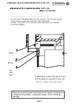
The buffer points are installed and secured using the enclosed springs. (see drawing)
The results of the check must be recorded in the check book
Page 40
Содержание 2.25 EMC
Страница 66: ...OPERATING INSTALLATION INSTRUCTION 2 POST LIFT Electric diagram for chain lifts H264 H265 Page 66 ...
Страница 67: ...OPERATING INSTALLATION INSTRUCTION 2 POST LIFT Electric diagram H342 Page 67 ...
Страница 68: ...OPERATING INSTALLATION INSTRUCTION 2 POST LIFT Electric diagram H325 Page 68 ...
Страница 69: ...OPERATING INSTALLATION INSTRUCTION 2 POST LIFT Electric diagram with rotary reversing switch Page 69 ...
Страница 70: ...OPERATING INSTALLATION INSTRUCTION 2 POST LIFT Electric diagram with push button Page 70 ...
Страница 71: ...OPERATING INSTALLATION INSTRUCTION 2 POST LIFT Page 71 ...
Страница 72: ...OPERATING INSTALLATION INSTRUCTION 2 POST LIFT Page 72 ...
Страница 73: ...OPERATING INSTALLATION INSTRUCTION 2 POST LIFT Page 73 ...
Страница 74: ...OPERATING INSTALLATION INSTRUCTION 2 POST LIFT Page 74 ...
Страница 75: ...OPERATING INSTALLATION INSTRUCTION 2 POST LIFT Page 75 ...
Страница 76: ...OPERATING INSTALLATION INSTRUCTION 2 POST LIFT Page 76 ...
Страница 77: ...OPERATING INSTALLATION INSTRUCTION 2 POST LIFT Page 77 ...
Страница 78: ...OPERATING INSTALLATION INSTRUCTION 2 POST LIFT Page 78 ...
Страница 79: ...OPERATING INSTALLATION INSTRUCTION 2 POST LIFT Page 79 ...
Страница 80: ...OPERATING INSTALLATION INSTRUCTION 2 POST LIFT Page 80 ...

