OPERATING & INSTALLATION INSTRUCTION 2-POST-LIFT
Installation and Commissioning H342
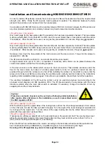
In order to install a lift perfectly correctly the concrete must be flat and horizontal and have the required
load strength (minimum BN 25). In accordance with EN1493 there must be a safety margin of 500 mm
minimum between the lift columns and any other obstacle (wall, etc) and, similarly, between any load to
raised and another obstacle.
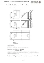
Lay out the base frame in the desired location so that the main column is on the right when seen from the
drive-on direction. The receiving plate for the chain break switch on the base frame will similarly be on the
right. It can then be assigned to the main column.
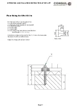
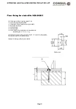
The base frame is anchored to the concrete with safety plugs or masonary screws AM16x200 DIN529-4.6 vz
(rust resistant steel). Torque of masonary screws M16 75 Nm, safety plugs M12 per manufacturer’s
instructions. The fixing bolts must be at least 150 mm deep into the concrete.
The masonary screws and plugs are not included.
The base frame must lie completely flat.
Bring the foot of the slave column (without control box) right up to the fixing point on the base frame.
Push the connecting cable through the cable conduit inside the column. It is important to keep some spare
length so that the column can be moved when tensioning the chain. The cable is then pulled further through
the cable canal in the base frame. The slave column is now set up. Secure the column with screws. The
cable must not be snagged or damaged.
The main column is put in place as described before. The end of the cable is pulled tight and then pulled
from below throught the column base plate and the conduit inside it. The cable for the chain break switch is
installed in the same conduit in advance. Set up the slave column, pull lossely secured cables and run them
through the back wall of the column to the control box.
Move the columns in the long holes with the smallest distance between them, bring the lifting carriage to the
same height and put on the chains. Shorten the chain as appropriate and connect to the enclosed chain
lock.
Move the main column outwards and screw it securely to the base frame. Move the slave column out using
the chain tensioning screw until the chain, removed from its guides, is sufficiently taut to allow it to be
squeezed together by hand so that the chain lengths touch.
Screw the slave column securely to the base frame. Torque value for the M16 screws, standard 8.8 = 200
Nm.
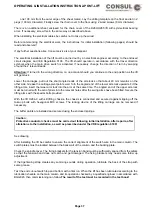
The litf columns should be vertical. On no account should they lean inward.
As slight outward leand (up to 10 mm) is desirable. If necessary extra shims (enclosed with accessories) can
be placed between the column base plates and the base frame for levelling purposes.
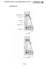
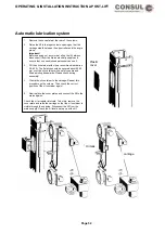
After completing the assembly of the chain break switch (the cable should be shortened as appropriate) and
the chain guide, the chain as well as the switch lever require greasing (see drawing).
Securing the lifting apparatus (eg, swivel arms) against accidental disconnection.
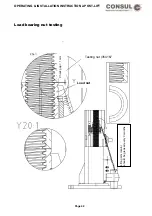
Secure the eye bearing with hexagonal safety screw on the take-up bolt so that there remains a gap of 1 to
2mm between the eye bearing and the screw head.
Page 39
Содержание 2.25 EMC
Страница 66: ...OPERATING INSTALLATION INSTRUCTION 2 POST LIFT Electric diagram for chain lifts H264 H265 Page 66 ...
Страница 67: ...OPERATING INSTALLATION INSTRUCTION 2 POST LIFT Electric diagram H342 Page 67 ...
Страница 68: ...OPERATING INSTALLATION INSTRUCTION 2 POST LIFT Electric diagram H325 Page 68 ...
Страница 69: ...OPERATING INSTALLATION INSTRUCTION 2 POST LIFT Electric diagram with rotary reversing switch Page 69 ...
Страница 70: ...OPERATING INSTALLATION INSTRUCTION 2 POST LIFT Electric diagram with push button Page 70 ...
Страница 71: ...OPERATING INSTALLATION INSTRUCTION 2 POST LIFT Page 71 ...
Страница 72: ...OPERATING INSTALLATION INSTRUCTION 2 POST LIFT Page 72 ...
Страница 73: ...OPERATING INSTALLATION INSTRUCTION 2 POST LIFT Page 73 ...
Страница 74: ...OPERATING INSTALLATION INSTRUCTION 2 POST LIFT Page 74 ...
Страница 75: ...OPERATING INSTALLATION INSTRUCTION 2 POST LIFT Page 75 ...
Страница 76: ...OPERATING INSTALLATION INSTRUCTION 2 POST LIFT Page 76 ...
Страница 77: ...OPERATING INSTALLATION INSTRUCTION 2 POST LIFT Page 77 ...
Страница 78: ...OPERATING INSTALLATION INSTRUCTION 2 POST LIFT Page 78 ...
Страница 79: ...OPERATING INSTALLATION INSTRUCTION 2 POST LIFT Page 79 ...
Страница 80: ...OPERATING INSTALLATION INSTRUCTION 2 POST LIFT Page 80 ...

