OPERATING & INSTALLATION INSTRUCTION 2-POST-LIFT
Emergency lowering I
Important:
During movements in emergency operation, there are not
automatic end switch-offs. Further movements as far as the
mechanical end stops may result in damage.
Notes:
The emergency lowering process described below must only
be carried out by authorised and trained personnel. A second
person must stand outside the danger area to monitor the
safety of staff and materals in the lifting platforma area.
At the first indication of any danger, the movement must be
stopped immediately. No further movement must take place
until the source of the danger has been removed. The only
permitted function is a single downward movement –however,
ensure that the load support equipment does not touch the
floor.
Emergency lowering
If the eectronic control system fails, it may be necessary to
carry out emergency lowering using to motor. If other
elemeents fail, carry out emergency lowering by hand (by
turning the big belt disc).
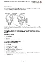
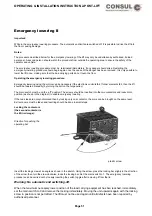
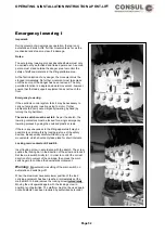
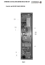
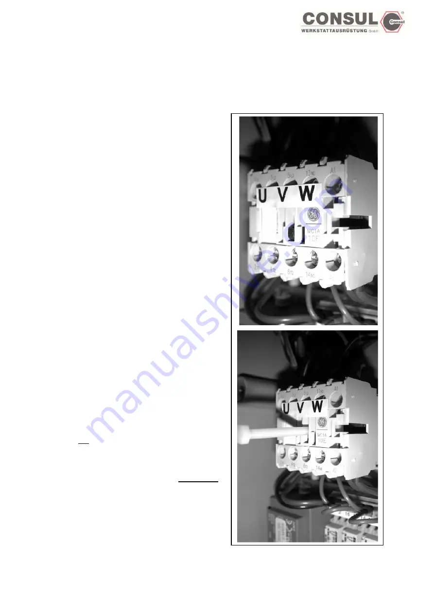
The main switch must be set to 0. As per the sketch, the
lowering contactors must be locked for a single emergency
lowering process by using the enclosed plastic screws.
If there is any uneveness in the lifting apparatus it may be
possible to overcome this by locking just one of the safety
devices, Be especially careful while carrying out all
movements, which should only take place for short intervals.
Locking main contactor K2 and K4:
Insert locking screw in accordance with the sketch. The screw
pushes the locking bar in the direction of the arrow and locks it.
Set the main switch briefly to 1 in order to control the correst
direction of movement of the carriage, then press the main
switch again to continue the downwards movement.
Warning:
No automatic resetting of the main switch, no
automatic end switching-off.
When the maximum necessary lower position of the load
carrying equipment has been reached, immediately set the
main switch to 0 and remove the locking screw immediately .
Moving the unit upwards again with the locking screw in
position is not permitted. The platform must not be used again
until all defects have been repaired by authorised personnel.
Page 52
Содержание 2.25 EMC
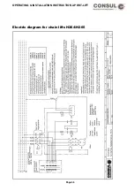
Страница 66: ...OPERATING INSTALLATION INSTRUCTION 2 POST LIFT Electric diagram for chain lifts H264 H265 Page 66 ...
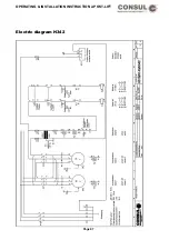
Страница 67: ...OPERATING INSTALLATION INSTRUCTION 2 POST LIFT Electric diagram H342 Page 67 ...
Страница 68: ...OPERATING INSTALLATION INSTRUCTION 2 POST LIFT Electric diagram H325 Page 68 ...
Страница 69: ...OPERATING INSTALLATION INSTRUCTION 2 POST LIFT Electric diagram with rotary reversing switch Page 69 ...
Страница 70: ...OPERATING INSTALLATION INSTRUCTION 2 POST LIFT Electric diagram with push button Page 70 ...
Страница 71: ...OPERATING INSTALLATION INSTRUCTION 2 POST LIFT Page 71 ...
Страница 72: ...OPERATING INSTALLATION INSTRUCTION 2 POST LIFT Page 72 ...
Страница 73: ...OPERATING INSTALLATION INSTRUCTION 2 POST LIFT Page 73 ...
Страница 74: ...OPERATING INSTALLATION INSTRUCTION 2 POST LIFT Page 74 ...
Страница 75: ...OPERATING INSTALLATION INSTRUCTION 2 POST LIFT Page 75 ...
Страница 76: ...OPERATING INSTALLATION INSTRUCTION 2 POST LIFT Page 76 ...
Страница 77: ...OPERATING INSTALLATION INSTRUCTION 2 POST LIFT Page 77 ...
Страница 78: ...OPERATING INSTALLATION INSTRUCTION 2 POST LIFT Page 78 ...
Страница 79: ...OPERATING INSTALLATION INSTRUCTION 2 POST LIFT Page 79 ...
Страница 80: ...OPERATING INSTALLATION INSTRUCTION 2 POST LIFT Page 80 ...


