background image

Notes:

Page 58 of 107

SmartLF Gx Service Manual

6.8.2 Aligning the Gx Cameras

If any one of the cameras has been removed, then ALL 5 cameras

will need to be aligned. It is very important that the cameras are all

looking  along  exactly  the  same  scan  line.  An  alignment  target  is

required  for  this  process,  and  this  is  purchasable  from

[email protected].  A  software  program  called  PlotWorks  is

also  needed  and  this  is  available  on  the  Gx  Service  CD  or  the

support website:

www.colortracsupport.co.uk

username: colortrac

password: service.

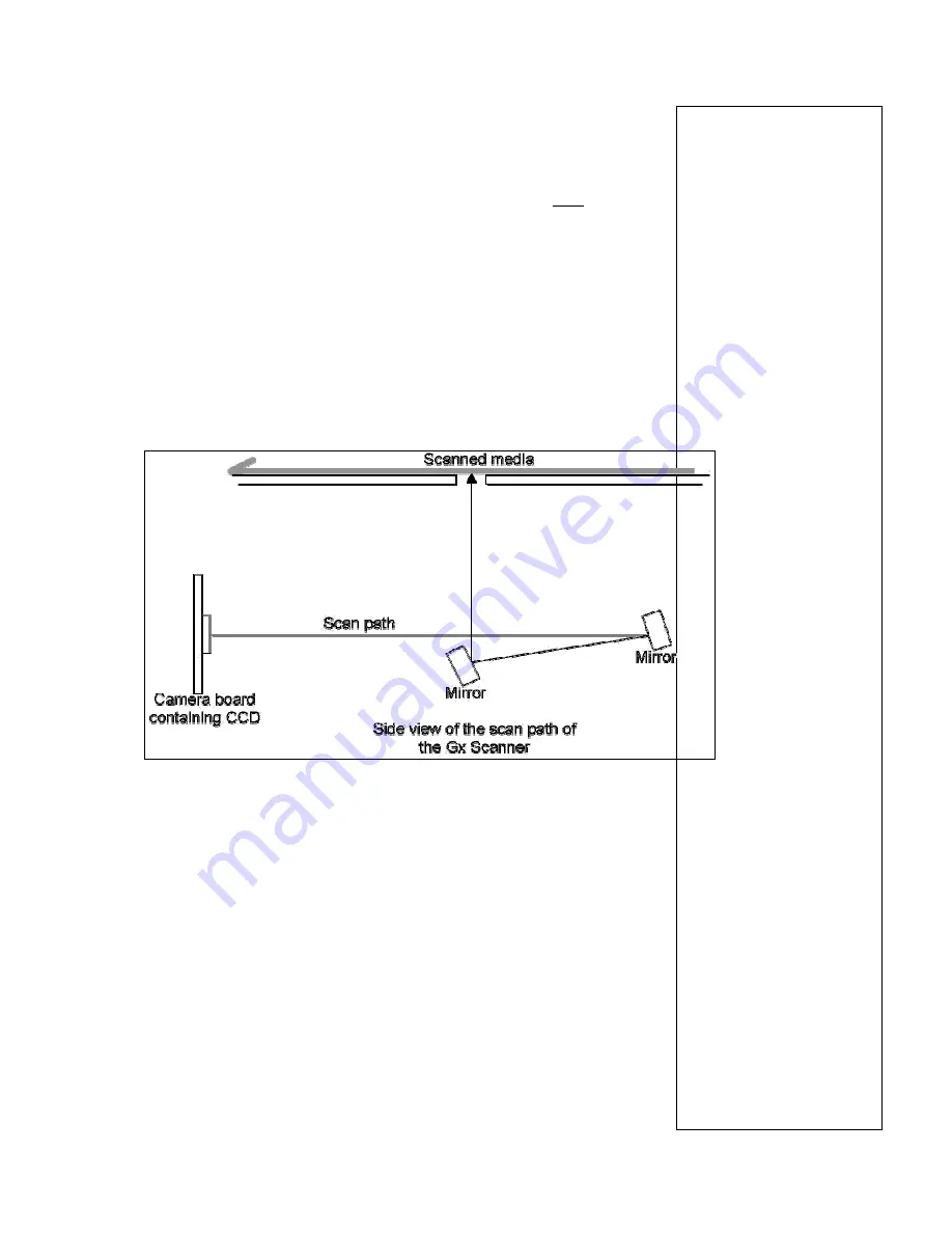
The CCD mounted on the camera board reflects off 2 mirrors and

up through the gap in the extrusion. The CCD needs to look exactly

along the scan path. By moving either end of the camera board one

way or the other, the line the camera sees is moved. If the camera

is not straight on the scan line the image can be distorted and look

incorrect during a scan

Содержание SmartLF Gx25c

Страница 1: ...I In nc c i in nc co or rp po or ra at ti in ng g T Ta an ng ge en nt t a an nd d A AN NA At te ec ch h C Co ol lo or rt tr ra ac c L Lt td d R Re eg gi is st te er re ed d n no o 2 24 44 43 30 08 87...

Страница 2: ...rac Ltd Kings Hall St Ives Business Park St Ives Huntingdon Cambridgeshire PE27 4WY United Kingdom Tel 44 0 1480 464618 Fax 44 0 1480 464620 www colortrac com Colortrac Ltd makes no warranty with resp...

Страница 3: ...Replacing Main Board 26 6 3 Replacing PSU 30 6 4 Replacing Lamp Ballast Board 36 6 5 Replacing Main Timing Belt 40 6 6 Removing Drive Rollers 44 6 7 Replacing Paper Sensors 48 6 8 Replacing Camera Uni...

Страница 4: ...tLF Gx25e GxT25e Enhanced Scan width of 25 Optical resolution of 1200 x 600dpi RGB 24 bit and 48 bit captured Mono and Greyscale scanning with enhanced speed SmartLF Gx42m GxT42m Monochrome Scan width...

Страница 5: ...Although Colortrac technical support group will do their best to help any service engineer in difficulties in the field we accept no responsibility if a non approved distributor engineer damages any p...

Страница 6: ...t the stand and 57Kg with the stand and is must have a minimum of two people to lift it safely ROTATING ROLLERS The scanner operates two sets of rollers to move the image across the scanner These roll...

Страница 7: ...e Manual 5 Removing Scanner Panels 5 1 Removing Left Hand End Cover 1 Remove the 5 x M5 pan head screws that hold the cover to the scanner 2 Remove the end cover and keep it in a safe place along with...

Страница 8: ...F Gx Service Manual 5 2 Removing Right Hand End Cover 1 Remove the 5 x M5 pan head screws holding the end cover to the scanner 2 Remove the end cover and keep it in a safe place along with the 5 x M5...

Страница 9: ...screws that are holding the panel in place It is recommended that the central screw is the last to be removed and even then it is not full removed until the access panel is supported 2 Supporting the...

Страница 10: ...Removing Rear Panels 1 Open rear access panel as described in chapter 5 3 Opening Rear Access Panel Page 9 2 Remove the 9 x M3 black anodised screws from the back of the scanner 3 Remove the black re...

Страница 11: ...Notes Page 11 of 107 SmartLF Gx Service Manual 4 Remove the 10 x M3 screws from inner rear panel 5 Remove the inner rear panel and store in a safe place for re assembly...

Страница 12: ...d cover as described in chapter 5 1 Removing Left Hand End Cover on page 7 2 Remove the Right Hand End Cover as described in chapter 5 2 Removing Right Hand End Cover on page 8 3 Remove the 2 x M5 pan...

Страница 13: ...ervice Manual 5 Remove paper tray extrusion from scanner and store in a safe place to prevent damage until re assembly 6 To remove the paper tray support extrusion first remove the 2 x M5 pan head scr...

Страница 14: ...ge 14 of 107 SmartLF Gx Service Manual 7 Remove the 2 x M5 pan head screws from the Left Hand end plate 8 Remove the paper tray support extrusion and store in a safe place to prevent damage until re a...

Страница 15: ...12 The support extrusion may not need to be removed unless it is being replaced 2 Remove extrusion cover as described in chapter 5 8 removing Extrusion Covers page 20 3 Remove the M5 pan head screw f...

Страница 16: ...F Gx Service Manual 5 Remove the 5 x M5 pan head screw from along the top of the extrusion that holds the paper tray to the scanner 6 Completely remove the paper tray and store in a safe place to prev...

Страница 17: ...SmartLF Gx Service Manual 5 7 Removing Scan Glass 1 Release the paper guide assembly by lifting the two catches at either end 2 Raise the PGA paper guide assembly open and secure with the safe lever o...

Страница 18: ...Notes Page 18 of 107 SmartLF Gx Service Manual 3 Using the special tool provided with every Gx scanner 4 insert the tool at one end of the scan glass into the slots near the glass...

Страница 19: ...prevent damage until re fitting NOTE If replacing the scan glass slot the cleaned new piece in place at this point making sure the edge with the largest chamfer goes towards the front of the scanner T...

Страница 20: ...er 5 7 Removing Scan Glass page 17 2 Remove 4 x M4 black pan head screw holding the cover over both ends of the lamps and remove covers at both ends storing them safely to prevent damage until re fitt...

Страница 21: ...ce Manual 4 Using you fingers as a pivot point apply pressure to the screw driver to prise the end of the cover off the extrusion 5 Using your finger tips work your way along the extrusion cover to pu...

Страница 22: ...tore in a safe place to prevent damage until re fitting Repeat the same procedure for the rear extrusion cover if necessary 7 To re fit the cover position the cover in the front lip and press down unt...

Страница 23: ...he cover over both ends of the lamps and remove covers at both ends storing them safely to prevent damage until re fitting 3 Using a 1mm or 1 5mm Allen key between the 2 pins of the tube rotate the la...

Страница 24: ...the pins are vertical use the 90 end of the Allen key to hook out the lamp 5 When fitting lamp back in or fitting new lamp make sure the lamp cap has the slot vertical at both ends of the scanner the...

Страница 25: ...press home Do not use unnecessary force that could brake the pins or lamp 7 Use the Allen key again to twist and lock the lamp into position NOTE After replacing the lamps the scanner will need to be...

Страница 26: ...ing Main Gx Board 1 Open the rear access panel as described in chapter 5 3 Opening Rear Access Panel page 9 2 Disconnect the power cable and motor control cable from the Main Combined Gx Board 3 Disco...

Страница 27: ...ing plate on each connector and pulling cable out being careful not to damage cable or break any of the wires by doing this 5 Remove the 2 x M4 pan head screws that are either side of the USB2 connect...

Страница 28: ...e is metallic tape fitted which stops stray EMC emissions from the Gx scanners make sure this tape is carefully removed from the old board and refitted to the board being fitting into the scanner 7 Fi...

Страница 29: ...Gx Board making sure the locking plate is up before fitting the cable blue plate towards the rear and wires showing at front into the connectors With the cable in correctly push the locking plate down...

Страница 30: ...wer cable and motor control cable to the Main Combined Gx Board 11 Close access panel as in chapter 5 3 Opening Access Panel page 9 6 3 Replacing Power Supply Unit 1 Remove the 7 x M3 pan head screws...

Страница 31: ...l 2 Carefully lift the cover away from the access panel but be aware that the fans are plugged in so do not try to take the cover away completely at this point 3 Disconnect the 2 x plugs from the fans...

Страница 32: ...Notes Page 32 of 107 SmartLF Gx Service Manual 4 Un plug the power out connector from the PSU 5 Un plug the power in connector from the PSU...

Страница 33: ...Notes Page 33 of 107 SmartLF Gx Service Manual 6 Remove the 4 x M4 screws holding the PSU to the access panel 7 Remove PSU from access panel and replace or store in a safe place until refitting...

Страница 34: ...anual 8 When fitting PSU to access panel insert the first M4 pan head screw in the top Right Hand corner making sure the earth cables are screwed between the PSU and the threaded post 9 Insert the rem...

Страница 35: ...he PSU as well as the power in and out connectors 11 Refit the cover making sure that there are no cables damaged or caught by the cover Insert all the screw to hold the cover in place 12 Close the ac...

Страница 36: ...trusion and Support Extrusion page 12 2 Remove the Paper Tray as in chapter 5 6 Removing Paper Tray page 15 3 The ballast for the Gx T 42 scanner is different than the Gx T 25 so be careful to fit the...

Страница 37: ...Notes Page 37 of 107 SmartLF Gx Service Manual 5 Remove the 2 x M4 pan head screws holding the ballast to the ballast bracket 6 Remove the ballast board from the scanner...

Страница 38: ...ment ballast board in place with the input in at the right hand side and screw down using the 2 x M5 pan head screws 8 Replace wires are had been removed by pressing down on the cable clamp buttons an...

Страница 39: ...10 Replace the Paper Tray as in reverse of chapter 5 6 Removing Paper Tray page 15 11 Replace the front support extrusion as in reverse of chapter 5 5 Removing the Paper Tray Extrusion and Support Ex...

Страница 40: ...r 5 1 Removing Left Hand End Cover page 7 2 Loosen the M4 nut on the end of the tension bar which will loosen the belt Slide the belt off the tension bar 3 Remove the belt from the roller drive pulley...

Страница 41: ...2 x M4 screws holding the support bracket in place 5 Move the support bracket down and off the bearing so that the belt can be fed around the bracket and removed To refit the new belt or replace this...

Страница 42: ...Notes Page 42 of 107 SmartLF Gx Service Manual 6 Feed the support bracket up over the bearing fitted on the raising mechanism 7 Reinsert the 2 x M4 screws to hold the raising mechanism in place...

Страница 43: ...e pulleys and the motor pulley before then feeding around the tensioning bar 9 While applying light pressure underneath the tensioning bar tighten the M4 nut up to lock the tension bar in place 10 Ref...

Страница 44: ...o lift the lid then disconnect the power again 1 Remove Right Hand End Cover as described in chapter 5 2 Removing Right Hand End Cover page 8 2 Remove Main Timing Belt as described in chapter 6 4 Repl...

Страница 45: ...Service Manual 6 Remove the 2 x M3 screws and washers holding the roller bearing in place on the Right Hand End plate 7 Push the bear off the roller shaft from the inside of the scanner towards the ou...

Страница 46: ...roller bearing in place on the Left Hand End plate Push the bear off the roller shaft from the inside towards the outside 9 Pull the roller shaft back so the end is as clear of the end plate as possi...

Страница 47: ...around this the sensor brackets may need to be loosened to allow the roller shaft to have that extra amount of movement Do not remove the screws from the sensor brackets completely just loosen them en...

Страница 48: ...y done so loosen the 2 x M3 screws holding the bracket to the scanner but do not take out completely then remove the M4 screw holding sensor to bracket 3 Remove the sensor When refitting the sensor ma...

Страница 49: ...of the chassis and an auto stitch procedure is carried out NOTE Do NOT attempt to try to repair the camera board from the unit 1 Open the rear access panel as described in chapter 5 3 Opening Rear Ac...

Страница 50: ...eath the scanner chassis inside the access panel When removing the unit hold the unit while removing any screws to prevent it from falling and being damaged 6 Remove the 4 x M3 nut from the top side o...

Страница 51: ...ac already magnified focused and aligned To achieve magnification the camera unit may have to have a different distance from the scan line of the scanner To get this distance M3 washers are used Each...

Страница 52: ...9 Position the replacement camera unit back into the scanner and hold in place making sure the adjustment washers are fitted before fitting in place 10 Replace the washers and M3 nuts to hold the came...

Страница 53: ...central to the extrusion gap If you can see move from one side than the other it is incorrect If the camera unit scan gap has equal showing through the gap in the scanner extrusion this is correct The...

Страница 54: ...un a full normalisation as described in chapter 8 3 Normalisation page 95 16 Run an autostitch as described in chapter 8 4 Auto stitch page 97 6 8 1 Replacing Gx Camera Board 1 Open the rear access pa...

Страница 55: ...Notes Page 55 of 107 SmartLF Gx Service Manual 4 Remove the camera ribbon cable from the camera requiring removal 5 Remove the 2 x M3 nuts on the camera board being removed...

Страница 56: ...Gx Service Manual 6 Remove the 4 x M3 pan head screws holding the board against the camera housing 7 Either unsolder the earth lead on the camera board or remove from the other end by removing the re...

Страница 57: ...d to be unsoldered from the board or if the replacement board has one attached will need to be removed from the other end 9 Refit or replace the camera board in the reverse way as it was taken off Mak...

Страница 58: ...trac com A software program called PlotWorks is also needed and this is available on the Gx Service CD or the support website www colortracsupport co uk username colortrac password service The CCD mou...

Страница 59: ...onnect the scanner to the laptop or PC if laptop not available and power both the PC and the scanner up If the plotworks program has not been install it can be done so from either the latest service C...

Страница 60: ...calibration target and close down the lid Make sure the dotted line of the target is central and straight along the scan line under the glass Make sure the whole target is central to the scan glass wi...

Страница 61: ...able 4 If PlotWorks has not already been installed on the PC attached to the scanner it can be done so in the normal way from either the Gx Service CD or the support site This installation does NOT pu...

Страница 62: ...n board 6 Before any alignment Un Normalise the scanner 7 Open the PC scope function Then select the camera requiring alignment Start with Camera 1 as all cameras will need alignment which ever camera...

Страница 63: ...stuck over the camera Focus area If the two lines are very close together then the camera will need focusing before alignment See next chapter Centre line of target must be inline with the centre line...

Страница 64: ...the dotted line of the target so is not looking central to the scan line Almost aligned The camera is seeing the dotted line but is looking diagonally across it Camera looking at the target line but i...

Страница 65: ...ocking screws that hold the camera to the mount have to be loose But not too loose so that the camera can move away from the mount a quarter of a turn should be enough to allow the camera to move up a...

Страница 66: ...show the correct image When in the process of walking the camera aligned when the image starts to show at one end carry on going between the 2 screws using small moments as have already been doing do...

Страница 67: ...the alignment looks to move out then stop tightening the screws re adjust the alignment as above and then continue tightening the locking screws Tighten the screws in opposite corners as shown in the...

Страница 68: ...adjusting then the alignment shown in previous chapter will need to be carried out afterwards 1 Attach the alignment target as described in the previous chapter as well as disconnecting the power cabl...

Страница 69: ...here is only 1 grub screw Be aware that once the grub screws are loose the alignment will move There may be a small chance that once the screws are re tightened the alignment may go back but if not th...

Страница 70: ...gger if turning the screw narrows the lines turn the screw the opposite direction until it starts to raise Turn the screw until the height of the focus line is at it s peek if the lines start to narro...

Страница 71: ...End Cover page 8 2 Disconnect all attached cables from the control board Using a pencil marking the connectors and keeping note of the position they were removed from 3 Carefully remove the ID chip fr...

Страница 72: ...l not to loose the 4 spacers that are fitted between the board and the control panel 5 Starting with the top Left Hand corner position the spacer back onto the M3 screw and position the board in place...

Страница 73: ...LF Gx Service Manual 6 Replace the ID chip if not already done so 7 Reconnect the cables to the control panel 8 Replace the Right Hand end cover in reverse order as described in chapter 5 2 Removing R...

Страница 74: ...ld down Roller 1 Open the paper guide assembly by releasing the catch at either end of the paper guide assembly 2 Remove the top cover by first removing the 2 x M3 CSK screws at either end of the top...

Страница 75: ...is in the way of removing the cover plate This needs moving first cut off the tie wrap holding the cable down This cable is only fitted to the raising lid units and is not present on standard lids 4 C...

Страница 76: ...Notes Page 76 of 107 SmartLF Gx Service Manual 5 Feed the sensor cable through the hole in assembly 6 Remove the 14 x M3 screws holding the cover plate and remove the plate and store safely...

Страница 77: ...oller spring bracket at either end of the paper hold down roller and store the bracket screws and spring in a safe place 8 On the underside of the paper guide assembly remove the 4 x M3 CSK screws tha...

Страница 78: ...es Page 78 of 107 SmartLF Gx Service Manual 9 Lift the brackets off from either end of the roller and store safely 10 Lift the paper hold down roller out of the unit removing the end from the timing b...

Страница 79: ...old down roller by loosening the grub screw in the pulley and re fit onto the replacement roller 12 Fit the new roller back into the timing belt and replace everything in the reverse order they were t...

Страница 80: ...down that the roller is actually flattened against the glass This set up must be carried out with the raising lid set down to its lowest point prior to adjustment being made 2 If the roller looks lik...

Страница 81: ...s to the raising lid version of Gx scanners which are labelled as the GxT scanner 1 Remove the Right Hand End Cover as described in chapter 5 2 Removing Right Hand End Cover page 8 2 Remove 2 x M4 Pan...

Страница 82: ...ehind the lifting bar NOTE During all this procedure make absolutely sure that the height of the lifting bar is not rotated at all and changed in away to prevent the paper guide being moved out of pos...

Страница 83: ...e 83 of 107 SmartLF Gx Service Manual 6 Feed the old belt around the lower mounting bracket to remove it 7 Fit the new belt around the lower mounting bracket making sure the teeth are on the inside of...

Страница 84: ...the pulley on the lifting bar NOTE If the belt is put on incorrectly then the mechanism will work in the operate direction to the other end of the paper guide assembly and damage the scanner so it is...

Страница 85: ...lifting bar and paper guide assembly it may be necessary to move the paper guide assembly slightly to line the holes up Tighten the pin back up 11 Refit the 2 x M4 Pan Head Screws into the top mounti...

Страница 86: ...iming belt Tighten the lower and upper bracket screws up finger tight so there is still a bit of movement in the lifting bar assembly 14 Re power the scanner if not already on and using the control bu...

Страница 87: ...3 Replacing Left Hand Raising Lid Belt 1 Remove the Left Hand end cover as described in chapter 5 1 Removing Left Hand End Cover page 7 2 Remove 2 x M4 Pan Head Screws from the lower bracket 3 Remove...

Страница 88: ...elt to loosen enough to free it from the pulley 5 Remove the timing belt from the pulleys and let the paper guide back down again NOTE During all the procedure make absolutely sure that the height of...

Страница 89: ...107 SmartLF Gx Service Manual 6 Feed the belt around the lower bracket to remove it totally from the scanner 7 Loop and feed the new belt around the lower bracket making sure the teeth on the belt ar...

Страница 90: ...e pulley to fit the belt on as this will mis align the whole paper guide assembly 9 It is important to make sure the belt goes back around the correct way as an incorrectly fitted belt will damage the...

Страница 91: ...of 107 SmartLF Gx Service Manual 10 Refit the 2 x M4 Pan Head Screws in the lower bracket and leave screws loose at the moment 11 Refit the 2 x M4 Pan Head Screws in the upper bracket and leave loose...

Страница 92: ...inger tight so there is still a bit of movement in the lifting bar assembly 13 Re power the scanner if not already on and using the control buttons move the lid up to the top and then down again this...

Страница 93: ...Notes Page 93 of 107 SmartLF Gx Service Manual 7 Voltages 7 1 PSU Output 5V 6V 32V 15V GND GRN GRN GRN 12V GRN 12V GRN...

Страница 94: ...rmalisation process and ability to check the driver and firmware of the scanner The passworded section is for distributors engineers to use and must not be given to an end user or customer without per...

Страница 95: ...utilities programs To run any of the utilities the scanner needs to have been on long enough to be in ready mode and pass the scanner warmup message on the display To run normalisation and stitch the...

Страница 96: ...otes Page 96 of 107 SmartLF Gx Service Manual 2 Click the Normalise Button 3 and insert the white normalisation sheet in to the scanner matt side facing downwards 4 Click to except the 5 Minute warnin...

Страница 97: ...target is longer than that please cut the length down to size If the target is missing damaged any good quality large format paper can be used making sure it is cut to 105 x 50cm 8 4 Auto Manual Stit...

Страница 98: ...nd entering the password pass or clicking the utilities button in bottom left hand corner 3 To auto stitch the scanner got the stitch tab and click the auto stitch button and agree to the any messages...

Страница 99: ...x 25 and set the Media Handling to rewind on Save delete ScanWorks and Gx Utilities both need to be left open during this adjustment 5 By pressing the scan button on the already opened ScanWorks the s...

Страница 100: ...stitch between the two CIS arrays Stitch values can only be positive numbers and the lowest denomination is 0 It is important that before re scanning the media the Set Stitch button MUST be press The...

Страница 101: ...orrect stitch point 1 2 then adjust CIS 3 to adjust the stitch point 2 3 and so on until all the CIS arrays are FB aligned 10 When you have finished adjusting the FB stitch between all the CIS arrays...

Страница 102: ...tself if the media handling is set to do so press scan if it looks worse try changing the value to go the other way from the original value and set stitch and re scan If it looked like the image was g...

Страница 103: ...Notes Page 103 of 107 SmartLF Gx Service Manual 14 When all the FB and LR stitch points look to be good exit the engineering menu software The scanner is now ready for use...

Страница 104: ...or Speed Used to set the motor speed in cases where the speed might need adjusting The motor speed is the time it takes the media to pass through the scanner correctly to create the right image length...

Страница 105: ...correct connection this program will measure the speed and inform you if it is correct or if you need to get USB2 compatibility This is also available to end users in the un passworded utilities 1 Cl...

Страница 106: ...es from the start menu and enter the stitch program by right clicking anyway within the control panel and entering the password pass 2 On the Driver installation page click on either the Install New F...

Страница 107: ...the utilities engineering panel on completion The Driver update will fail to update through utilities on some PC s and will need to have the driver updated in the PC Device Manager NOTE The latest fir...

Отзывы: