background image

91b_1_5 en bedingt.fm, 10.09.2010

P1890E/EN 2010-08

11

Product description

3

2.3

Storage

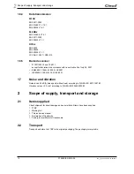
For short-term storage and for protection against damage:

Place the 17BP in the tool holder.

For storage longer than 100 hours:

Disconnect battery from the 17BP.
The battery is discharged by the electronics integrated in the tool.  

3

Product description

3.1

General description

Sturdy, brushless motor with resolver.
 Shutoff is torque/angle-controlled.

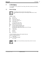
LCD display with information on status, torque and angle.

Green OK and red NOK LED display provides information
on the current fastening result.

LED lighting makes it possible to find the screw point quickly.

Clockwise/counterclockwise rotation

Low vibration level

Servo and fastening electronics are integrated in the 17BP.

Fastening parameters are set with the controller or to a computer.

Data is transmitted between the controller and tool via 
-

infrared (IrDA)
Parameters and rundown results are transmitted to the control or to a computer simply by placing the 
17BP in the tool holder.

-

868 MHz

-

WLAN (IEEE 802.11b/g)

-

RF15.4 (IEEE 802.15.4).

Power supply via 
-

Akkupack 26 V / 44 V

-

Power Modul 48 V

Built-in acoustic signal. The signal is activated after barcodes are scanned. It can also be activated after 
NOK rundowns for a programmable time.

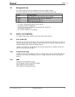
Object

Time period 

Storage temperature

17BP

 without PS

No guideline

-25 °C to +40 °C (-13 to 104 °F)

Содержание 17BP B

Страница 1: ...For additional product information visit our website at http www apextoolgroup com 17BP B Cordless EC Tool Instruction Manual P1890E EN 2010 08...

Страница 2: ...4E programming manual controller TMEB 200 no P1895E programming manual TMEB COM no P1898E for PC application Programming manual Nutrunner control m Pro 400S SE Programming manual Nutrunner control mPr...

Страница 3: ...r otherwise without the express permission of Cooper Power Tools GmbH Co OHG 17BP represents all models of the cordless EC tool as described here PS represents all models of power supply as described...

Страница 4: ...4 P1890E EN 2010 08 90a_ Deckblatt en fm 10 09 2010...

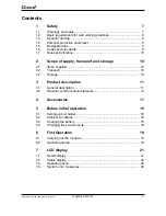
Страница 5: ...rt and storage 10 2 1 Items supplied 10 2 2 Transport 10 2 3 Storage 10 3 Product description 11 3 1 General description 11 3 2 Operation and functional elements 12 4 Accessories 17 5 Before initial o...

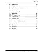
Страница 6: ...ubricants 40 8 4 Disassembling gear 40 9 Troubleshooting 41 10 Spare parts 49 10 1 Gear 50 10 2 Tool holder optional 52 10 3 Fixture order list 53 11 Technical data 55 11 1 Dimensions of 17BP 55 11 2...

Страница 7: ...ich if not avoided may result in minor or moderate injury or property and environmental damage If this warning is not observed injuries property or environmental damage may occur Class 2 laser product...

Страница 8: ...e 17BP only with power supply PS by Cleco Safety of persons The head can close when pushing the start button inadvertently eg when putting down the tool Fin gers can be bruised or severed Do not reach...

Страница 9: ...device may not cause harmful interference and 2 this device must accept any interference received including interference that may cause undesired operation Changes or modifications not expressly appr...

Страница 10: ...of July 26 2001 EN60825 1 1994 A1 2002 A2 2001 IEC60825 1 1993 A1 1997 A2 2001 1 7 Noise and vibration Noise level 60 dB A free speed without load according to DIN EN ISO 4871 1997 03 Vibration value...

Страница 11: ...D lighting makes it possible to find the screw point quickly Clockwise counterclockwise rotation Low vibration level Servo and fastening electronics are integrated in the 17BP Fastening parameters are...

Страница 12: ...of their respective item nos Item Designation F1 F2 Function keys 2 LED display 3 Start button 4 Reverse switch 5 IrDA infrared interface port 6 Set torque stick on marking foil 7 LED lights for fast...

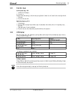
Страница 13: ...pressed 3 2 2 LED display The LED display shows the respective operating status and the result of the last fastening sequence see 6 2 Operating status page 19 Software update During Software Update th...

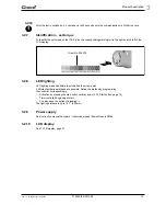
Страница 14: ...ce the 17BP in the tool holder with IrDA inter face port Order no 935144 Data transmission is possible in the Active Energy saver mode and Standby operating modes but not possible in Sleep see 6 2 Ope...

Страница 15: ...ods are possible Define the method by programming the controller correspondingly Activation by pressing the start button halfway down 3 2 3 Start button page 14 Time controlled beginning at start You...

Страница 16: ...ful scan is acknowledged by an acoustic signal Press the start button on the tool again this starts the rundown Alternative Assign the Read barcode function to the left function key F1 on the tool Pre...

Страница 17: ...der no 961350 Adapter cable Order no 961341 030 3 m Order no 961341 060 6 m Order no 961341 080 8 m Order no 961341 100 10 m Extension cable Order no 961342 030 3 m Order no 961342 060 6 m Order no 96...

Страница 18: ...erface port Select the location in such a way that no outside light shines onto the tool holder This can inhibit data transmission Lay the connection cable in such a way that there is no danger that p...

Страница 19: ...ller Types without wireless transmission must be placed in the tool holder when the rundown is complete The rundown results are transmitted and shown under the Run screen menu item 6 2 Operating statu...

Страница 20: ...20 P1890E EN 2010 08 91b_1_5 en bedingt fm 10 09 2010 First Operation 6...

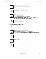
Страница 21: ...OK Result is not OK OFF Torque encoder offset error CAL Torque encoder calibration error ENC Angle encoder error IP Current overload in output section IIT Requested motor output is too high TMAX Maxim...

Страница 22: ...wns can be carried out All fastening sequences have been completed Synchronize the tool with the control once again No fastening sequences have been initialized Synchronize the tool with the control o...

Страница 23: ...in the timeout or an invalid barcode was read The display switches to Expect barcod Scan the barcode in again First line The next position to be fastened Second line Number of positions Third line Num...

Страница 24: ...y F2 The menus can be disabled by configuring appropriate parameter in the controller Basic functions F2 Activate main menu F1 Go to previous menu item F2 Go to next menu item Press F1 longer than 2 s...

Страница 25: ...RF settings Software version Back Servo Emergency strategy Back Diagnostics TQ calibration TQ measurement Angle encoder Voltages Speed Back Set position Next position Reset Linking Back Scanner Read b...

Страница 26: ...n Signal RSSI Back Administration General items such as Date Time Counter display etc Diagnostics Diagnostic functions for the tool Position Selects the position to be used next Scanner Deletes a prev...

Страница 27: ...ftware version Servo software version Displays the installed software version NOTE The emergency strategy can be enabled only if this is enabled on the control See Advanced Application Builder System...

Страница 28: ...or Linking operating mode all steps are used with the corresponding parameters of the last selected Tightening Group The memory of the tool stores data from up to 512 rundowns If more rundowns than th...

Страница 29: ...to 360 degrees it is evaluated and displayed as OK Monitoring criteria are the torque and a monitoring time If the torque exceeds 15 of the calibration value even during the dwell time or if the monit...

Страница 30: ...d next You can skip the position You can select the position to be used next using the function keys F1 Activate the previous position F2 Activate the next position Press the start button or F2 longer...

Страница 31: ...acters are displayed When the start button is pressed the current wireless signals are displayed 17BPX N Signal strength S Signal strength dBm Displays the installed software version of the wireless m...

Страница 32: ...xt menu item Press F1 longer than 2 seconds to delete the selection and exit the menu NOTE The network ID must match the set network ID of the base station Displays the tool ID and allows you to confi...

Страница 33: ...10 and 25 mW for the transmission power If channel 2 or 3 is selected you can choose either 1 or 5 mW for the transmission power Press the start button or F2 longer than 2 seconds to accept the selec...

Страница 34: ...a channel from 1 4 Start button show tool ID default 1 F1 Activate a lower network ID F2 Activate a higher network ID Press the start button or F2 longer than 2 seconds to accept the selection and di...

Страница 35: ...show encryption default off F1 Activate On Press the start button or F2 longer than 2 seconds to accept the selection and display the next menu item Press F1 longer than 2 seconds to delete the selec...

Страница 36: ...knowledged and must be returned to the manufacturer for repair Initialization error in tool servo Remove the battery and then re insert it If this does not help Return tool to Sales Service Centers fo...

Страница 37: ...urn tool to Sales Service Centers for repair Tool angle encoder is sending incorrect signals to the servo amplifier Return tool to Sales Service Centers for repair Warns that battery is running low Re...

Страница 38: ...ol to Sales Service Centers for repair Transducer offset voltage error Tool was not discharged at time of calibration Allow tool to discharge and try again If this does not help Return tool to Sales S...

Страница 39: ...the tool into account CAUTION Danger of injury due to unintentional activation before service disconnect the 17BP from the battery After fastening cycles1 1 For the number of fastening cycles refer to...

Страница 40: ...er no Packing unit DIN 51502 Nye Lubricants Inc Dow Corning 933027 1 kg KP1K Microlube GL 261 a Carefully clamp the 17BP on the pistol grip in a vice with plastic jaws Remove the countersunk screw ord...

Страница 41: ...ring tightening sequence high torque is required for example with coated screws If high torque is required for a longer period of time e g for several turns then the number of rundowns with one batter...

Страница 42: ...of the tool to the address list of the access point The MAC address of the tool is displayed on the corre sponding label above the battery and in the WLAN RF settings submenu A firewall blocks port 4...

Страница 43: ...the settings are changed it is necessary to press Accept F1 in order to apply the settings Check that the serial cable is connected to the selected port Selected port is used for serial data transmiss...

Страница 44: ...e the same first three num bers for the IP addresses on both the controller and base station E g IP address controller 192 168 1 xxx IP address base station 192 168 1 xxx Subnet mask 255 255 255 000 A...

Страница 45: ...wer of the tool Too much traffic on the same channel Reduce traffic on the wireless network Deacti vate torque plot data transmission Too many tools on the same channel Use different channels for diff...

Страница 46: ...ocol is set to anything except NONE and whether the same port is being used If so select a different port or disable serial data transmission Check all available tools as necessary The same port canno...

Страница 47: ...RF commu nication is too short Output power is too low Increase the output power of both the base sta tion and the tool Location of the base sta tion bad Move the base station to a location where the...

Страница 48: ...48 P1890E EN 2010 08 91e_Trouble shooting en bedingt fm 10 09 2010 Troubleshooting 9...

Страница 49: ...parts 10 10 Spare parts Note Use only original Cleco spare parts Failure to comply can result in reduced power and increased service requirements If spare parts not manufactured by us are installed th...

Страница 50: ...10 10 1 Gear Typ 85 56 3 58 60 3 62 90 17BP B05Q 935101 541894 542230 541894 935599 541899 17BP B07Q 935102 542233 541897 935598 17BP B09Q 935103 541893 542231 541894 935599 17BP B13Q 935104 542232 54...

Страница 51: ...90e_Ersatzteile en fm 10 09 2010 P1890E EN 2010 08 51 Spare parts 10 1 Order no 2 Quantity 3 Dimensions Recommended spare part for every five 5 tools See table page 50...

Страница 52: ...eile en fm 10 09 2010 Spare parts 10 10 2 Tool holder optional 101 103 97 96 98 99 100 102 OFF 0 5 0 7 Nm 0 4 0 55 lbf ft Loctite 274 320595 SW 4 OFF 5 6 Nm 3 7 4 4 lbf ft 912926 SW 5 Order no IrDA 98...

Страница 53: ...90E EN 2010 08 53 Spare parts 10 1 Order no 2 Quantity 3 Dimensions See table page 52 10 3 Fixture order list Order no Description 933467 Assembly circlip 67 933468 Base 933469 Awl 933470 Sleeve 93333...

Страница 54: ...54 P1890E EN 2010 08 90e_Ersatzteile en fm 10 09 2010 Spare parts 10...

Страница 55: ...26 9 17BPB07Q 17BPB09Q 17BPB13Q 17BPRB05Q 308 281 1 296 7 14 2 17BPXB05Q 17BPZB05Q 17BPRB07Q 17BPXB07Q 17BPZB07Q 17BPRB09Q 17BPXB09Q 17BPZB09Q 17BPRB13Q 17BPXB13Q 17BPZB13Q With scanner Typ L1 1 L1 2...

Страница 56: ...56 P1890E EN 2010 08 90g_TechnDaten en fm 10 09 2010 Technical data 11 11 2 Dimensions of tool holder optional Abb 11 1Dimensions of tool holder mm...

Страница 57: ...n rpm rpm mm kg ft lbf Nm 1 degrees 17BPB05Q 3 7 5 2 2 3 1639 2428 M4 1 36 4 7 6 41 0 7322 17BPRB05Q 1 46 17BPXB05Q 17BPZB05Q 17BPRSB05Q 1 52 17BPXSB05Q 17BPZSB05Q 17BPB07Q 5 2 7 2 2 3 1161 1721 M5 1...

Страница 58: ...4 2 Control electronics 11 4 3 IrDA interface port Features Data Nominal motor phase current 8 A peak value sine Rated output 150 VA Maximum power 500 VA Features Data Rated voltage 26 V Nominal curre...

Страница 59: ...on the width of the barcode Laser safety Laser class 2 IEC 60825 EMI RFI FCC Part 15 Class B EN 55024 CISPR 22 AS 3548 VCCI Barcode Typen UPC A UPC E UPC E1 Trioptic Code39 Interleaved 2of5 Discrete 2...

Страница 60: ...ption WPA WPA2 802 11 128 bit TKIP CCMP encryption 802 1x EAP authentication LEAP PEAP TTLS GTC MD5 OTP PAP CHAP MSCHAP MSCHAPv2 TTLS MSCHAPv2 Pre shared key mode PSK Range Typically up to 50 m 164 0...

Страница 61: ...tion data update is carried out properly 13 Disposal Precision class 0 5 of final value Linearity error 0 25 of final value Measurement range 125 to 125 of final value CAUTION Injuries and environment...

Страница 62: ...1718 Fax 425 497 0496 Fax 717 757 5063 Tel 905 501 4785 Fax 905 501 4786 Germany England France China Cooper Power Tools Cooper Power Tools Cooper Power Tools SAS Cooper China Co Ltd GmbH Co OHG GmbH...

Отзывы: