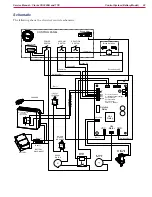
Control System (Battery Model)
24
Service Manual – Clarke CA30 20B and 17E
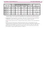
Charger and Power
Switch Status
Voltage between Machine Enable and +Com
Charger relay
resistance w/o
control board
‡
Normal
Open circuit at
Controller
Open circuit at
charger
Short Circuit
†
Charger = off
Power = off
0 V
0 V
0 V
0 V
0 Ω (short)
Charger = off
Power = on
0 V
0 V
24 V
0 V
N/A
Charger = on
Power = off
0 V
0 V
0 V
0 V
∞
Ω (open)
Charger = on
Power = on
24 V
0 V
24 V
0 V
N/A
† Column-4, Short Circuit isn’t specifically applicable to the scenario because the machine would be
functioning. However, the machine would also be fully functional when the charger was plugged in.
‡
Important:
To avoid damaging your multimeter, make sure to disconnect the control board before
checking the resistance of the charger relay contacts. Leave the machine turned off.
• The
Red
entries in the table above are the measurements that are indicative of the associated failure
modes.
•
If all of your measurements show 0 volts (columns 2 and 4 above), turn the machine power off,
disconnect the wires, and measure the resistance of the relay contacts in the charger with the charger
unplugged and then plugged in. Compare these to the results in the last column of the table above.
•
Briefly jumper the two wires together and turn the machine on. If the machine functions normally,
then the battery charger is faulty and needs to be replaced.


