background image

Control System (Corded Model)

14

Service Manual – Clarke CA30 20B and 17E

Solution Solenoid

The solution solenoid is a 120-volt magnetically controlled valve that permits fluid to gravity-flow to the 

scrub deck. Power to the solenoid first passes through the main power switch, then the solution switch. 

The neutral conductor passes straight to the solenoid, but the line-side conductor passes through the scrub 

control relay before going to the solenoid. (See 

Scrub Control Relay

 described on page 15 for a description 

of the scrub function.) This series connection causes the solution solenoid to be active only if the scrub 

system is active. No solution will flow unless the brush is also active.

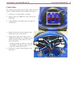
Brush Motor and Starter

The brush motor is a single-phase induction motor with a separate start winding to get the motor up to 

operating speed. An analogy for this type of motor is the pedals on a bicycle, where the pedals are positioned 

straight up-and-down, and can’t be started until the pedals are moved slightly past-center. The start 

winding is used to “pull the pedals (motor winding) past center” so normal magnetism can cause complete 

rotation. 

The power through this start winding needs to be slightly delayed (electrically) from the main AC power, 

which is accomplished with capacitors. When the motor is already running at-speed, the “Run Capacitor” 

provides sufficient delayed-power to the start winding to keep the motor spinning past this “straight up-

and-down” position. However, when the motor is just getting started, it needs a little extra power (extra 

kick) in the start winding to get moving. This is provided by an additional, larger capacitor, called a “Start 

Capacitor”. During start-up, the Run capacitor and Start capacitor combine to give this extra amperage to 

the start winding to begin to turn. However, this extra current 

in the start winding would be too much current when running at 

normal speed, so the Start capacitor must be disconnected from 

the motor once it begins to turn near operating speed. This is the 

function of the “Motor Start Relay”.

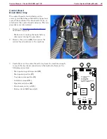
Motor Start Relay

The motor start relay controls when the start capacitor is 

connected to the brush motor. The start capacitor needs to be 

connected during startup, but to prevent too much current in 

the winding, it must be disconnected once the motor is up to 

speed. The start relay is a voltage-controlled relay that turns off 

(normally closed contacts open) once a prescribed voltage has been 

reached at its coil. This relay senses when the voltage of the Start 

Winding has reached its operating voltage, and then disconnects 

the start capacitor.

The most common failure-mode of a capacitor-start, capacitor-run motor is failure to achieve operating 

speed. Refer to the 

Troubleshooting

 described on page 16, but this is most commonly caused by a failure of 

the start capacitor.

BRUSH 

MOTOR

MOTOR 

START RELAY

LINE 1

NEUTRAL

RUN

START

V

START 

WINDING

Содержание CA30 17E

Страница 1: ...Clarke CA30 20B and 17E 12 15 Revised 2 16 Form No 56043171 Service Manual Model numbers CA30 20B CLARKE510B CA30 17E CLARKE430C English ...

Страница 2: ...10 CA30 20B 10 CA30 17E 11 Control System Corded Model 12 Functional Description 12 Control Panel 12 Schematic 13 Main Power 13 Vacuum Motor 13 Solution Solenoid 14 Brush Motor and Starter 14 Motor Start Relay 14 Scrub Control Relay 15 Troubleshooting 16 Whole Machine Not Functioning 16 Removal and Installation 17 Rear Covers Control Cover 17 Control Panel 18 Relays and Brush Motor Capacitors 19 C...

Страница 3: ...20B 36 Weak Suction 36 Removal and Installation 37 Vacuum Motor 37 Replacement Notes 38 Vacuum Motor Brushes 39 Scrub System 41 Functional Description 41 Troubleshooting 42 Brush Motor 17E 42 No Power 42 Low Speed lack of Power or Overheating 42 Start Relay Troubleshooting Voltage Readings 43 Scrub System 17E 44 Brush Motor 20B 45 Removal and Installation 46 Scrub Deck 46 Replacement Notes 47 Brus...

Страница 4: ... Service Manual Clarke CA30 20B and 17E Squeegee System 55 Functional Description 55 Troubleshooting 55 Floor Streaks 55 Maintenance and Adjustment 56 Squeegee Blade Changing 56 Squeegee Trim Adjustment 58 ...

Страница 5: ...manual carefully before performing any maintenance and repair procedure on the machine Other Reference Manuals and Information Sources Document Name Document Number Document Type CA30 17E Instructions for Use 56091131 User Manual Parts List CA30 20B Instructions for Use 56091130 User Manual Parts List Parts And Service Service and repairs must be performed only by authorized personnel or Nilfisk S...

Страница 6: ...s machine should be used only by properly trained and authorized persons Do not operate the machine near toxic dangerous flammable and or explosive materials This machine is not suitable for collecting dangerous or hazardous materials In case of fire use a powder fire extinguisher not a water based extinguisher Do not use on surfaces having a gradient exceeding that marked on the machine While on ...

Страница 7: ...comes equipped with a short power cord and must be used with an additional extension power cord This extension cord must be of the appropriate type size and length as described below The cord must be a 3 wire including ground flexible cord with a minimum length of 15 feet The cord type letter designations must have S or SJ as the first digits but cannot have SV or SP as the first digits Additional...

Страница 8: ...n 200mm 8 in Diameter of guide wheel 63 5mm 2 5 in 63 5mm 2 5 in Power of vacuum system motor 350w 400w Maximum gradient when working 2 Max 2 Max Sound pressure level at workstation 70dB A 3dB A 72dB A 3dB A Standard batteries 2 12V 24V 105Ah AGM N A Power Cord Length N A 20m Battery compartment size W x L x H 340 x 330 x 260mm N A Vacuum system circuit capacity 1200 mm H2O 1200 mm H2O Cleaning wi...

Страница 9: ...s X Inspect pad brush X Clean solution and recovery tanks X Inspect power cord corded model X Inspect squeegee blades for damage X Clean the solution filter X Inspect for loose fasteners and electrical connections X1 Inspect replace scrub motor brushes battery model X Inspect replace vacuum motor brushes X 1 Also perform this inspection after the initial 10 hours of new machine usage ...

Страница 10: ...ivot 21 Brush Pad Holder 30 Battery Low LED 4 Serial Number Plate 13 Squeegee Adjust 22 Solution Sight Tube 31 Battery Level LEDs 5 Control Cover 14 Squeegee Thumbscrews 23 Shut Off Float 32 Power Switch 6 Charging Indicator 15 Squeegee Clip 24 Vacuum Motor 33 Vacuum Switch 7 Circuit Breakers 16 Squeegee Blade 25 Brush Motor 34 Solution Switch 8 Battery Disconnect 17 Recovery Tank Lid 26 Wheels 35...

Страница 11: ...3 Control Panel 12 Squeegee Pivot 21 Brush Pad Holder 30 N A 4 Serial Number Plate 13 Squeegee Adjust 22 Solution Sight Tube 31 N A 5 Control Cover 14 Squeegee Thumbscrews 23 Shut Off Float 32 Power Switch 6 N A 15 Squeegee Clip 24 Vacuum Motor 33 Vacuum Switch 7 Circuit Breakers 16 Squeegee Blade 25 Brush Motor 34 Solution Switch 8 Power Cord 17 Recovery Tank Lid 26 Wheels 9 Lower Cover 18 Recove...

Страница 12: ...r inputs through switches and activates various solenoids and relays to control components Most of the components operate at line voltage except for the scrub switches and scrub control relay which operate at 24 volts DC Control Panel The control panel contains the operator controls including the scrub switches located in the handle of the machine Scrub Switches Solution Switch Power Switch Vacuum...

Страница 13: ...ugh a resettable circuit breaker for circuit overload protection All power to the remainder of the machine passes through the main power switch in the control panel which switches both line and neutral conductors to the rest of the system All downstream functions are in series with this circuit breaker and switch Vacuum Motor The vacuum motor receives its power from the main power switch It too sw...

Страница 14: ...vides sufficient delayed power to the start winding to keep the motor spinning past this straight up and down position However when the motor is just getting started it needs a little extra power extra kick in the start winding to get moving This is provided by an additional larger capacitor called a Start Capacitor During start up the Run capacitor and Start capacitor combine to give this extra a...

Страница 15: ...the solution system is active or not active when the brush is active The scrub control relay is acting as the primary motor contactor for the brush motor but a second set of contacts also functions to enable the solution solenoid circuit This prevents the solution solenoid from being active when the brush motor is not also active SOLENOID SWITCH POWER SWITCH 24V DC Power Supply Brush Switches 24V ...

Страница 16: ...ircuit protection device GFC GFCI make sure the device such as receptacle or GFCI breaker has not tripped Inspect the power cord or extension cord for damage and loose bent broken prongs Check the machine on board circuit breaker for trip by pressing in on the button With the power cord removed remove the control panel and inspect for loose wires at the main power switch as well as the remaining s...

Страница 17: ...achine entirely you will need to remove the squeegee lift cable F Remove the bolt G and remove the cable 4 Free the recovery drain hose from its clip and lay it to the side 5 Remove the 6 screws C that secure the upper A and lower B covers to the machine The 2 screws D at the top of the lower cover do not need to be removed at this time but may be removed later if you wish to separate the upper an...

Страница 18: ...put wires from the power supply board The polarity of the wires is not critical to the function of the power supply 5 Unplug the DC output connector from the power supply 6 Using tape or similar label make note of which wiring bundles are connected to each of the 3 switches and remove the 4 wires from each switch During replacement take care not to mix the line and neutral wires on each side of th...

Страница 19: ...ar Covers Control Cover described on page 17 4 Remove the 2 screws A that secure the capacitor holder B to the machine and carefully lower the assembly and wires out of the machine 5 Remove the screw E that secures the motor starter F 6 Loosen the 2 screws and nuts G that secure the scrub relay H 7 Simultaneously slide out both capacitors by pushing up on them through the holes in the bottom of th...

Страница 20: ...ndicator Solution Switch Battery Charge Level Main Power Switch Hour Meter Vacuum Switch Main Power Switch The main power switch controls power to the main control board and the hour meter For the hour meter both the positive and negative power leads are switched For the control board only the negative power lead is switched Positive power is always present at the control board but passes through ...

Страница 21: ... switches the negative power to the solenoid The solution solenoid is active only when the solution switch is closed and at least one of the brush switches are closed This causes the solution solenoid to be active only if the scrub system is active No solution will flow unless the brush is also active Brush Motor The brush motor is controlled by a power relay adjacent to the control board The posi...

Страница 22: ... SOLUTION SOLENOID Scrub Active S2 Vacuum S3 Common Solution S4 7 7 Hour Meter Scrub Active GND Vac Motor VCC COM S2 S3 S4 C C SOLUTION Vac Relay Solution Relay COM C Common C Machine Enable Charger S4 Solution SW S3 Vacuum SW S2 Scrub SW C Com Common Battery Meter BATTERY CHARGER 30A 30A BATTERY DISCONNECT Common Machine Enable MACHINE ENABLE NORMALLY CLOSED RELAY BRUSH CIRCUIT BREAKER Batt Switc...

Страница 23: ...not tripped by pressing in on the button Remove the Rear Covers Control Cover described on page 26 and begin checking voltages starting at the main power switch and working back toward the batteries 4 Unplug the battery disconnect and measure the battery voltage to ensure the batteries are not fully depleted Reconnect the plug when done 5 If the red LEDs below the battery icon do not illuminate fo...

Страница 24: ... fully functional when the charger was plugged in Important To avoid damaging your multimeter make sure to disconnect the control board before checking the resistance of the charger relay contacts Leave the machine turned off The Red entries in the table above are the measurements that are indicative of the associated failure modes If all of your measurements show 0 volts columns 2 and 4 above tur...

Страница 25: ... battery power at the main power switch 24V between terminals Note that these switch terminals will provide convenient battery reference test points for the remaining examinations 2 Verify outgoing power at main switch Terminal to terminal should be 0 volts when the switch is off and 24 volts when the switch is on 3 Verify that the control board is providing Com at the vacuum solution and brush sw...

Страница 26: ...lt G and remove the cable 4 Free the recovery drain hose from its clip and lay it to the side 5 Remove the 6 screws C that secure the upper A and lower B covers to the machine The 2 screws D at the top of the lower cover do not need to be removed at this time but may be removed later if you wish to separate the upper and lower covers During reassembly you may find it easier to install the covers s...

Страница 27: ... lift the control panel up to expose the wiring below 4 Remove the battery meter connector from the battery meter circuit board 5 Using tape or other label make note of which wiring bundles are connected to each of the 3 switches and remove the wires from each switch During replacement take care not to mix the positive and negative wires on each side of the main power switch 6 Unplug the 3 wire te...

Страница 28: ...tery disconnect during the procedure 2 Remove the 4 screws B that secure the control board enclosure to the machine 3 Carefully move the control board away from the machine enough to reach the electrical connections on the back side Remove the following connectors Main power negative ground D Main power positive F Vacuum motor positive E Solution solenoid G Operator switches H Brush motor relay co...

Страница 29: ...ires K from the brush relay M 5 Remove the two power wires L from the brush relay 6 Remove the 4 screws Q that secure the control board P to the enclosure A and remove the control board 7 Remove the 2 screws N that secure the brush relay M to the enclosure and remove the relay M K L M A N P Q ...

Страница 30: ...e procedure Remove the squeegee lift cable F in the procedure Unplug the main battery disconnect in the procedure 3 Route the vacuum hose A and recovery drain B through the operator s handle to keep them out of the way during the procedure 4 Remove the 2 screws C that secure the battery retaining bracket E and remove the bracket 5 Position a platform or lift G in back of the machine that matches t...

Страница 31: ...s to the new batteries Make sure to connect this from positive to negative between the two batteries Torque the terminal bolts to 7 1 8 0 ft lbs 85 95 in lbs or 9 6 10 7 N m 10 Remove the terminal bolts and transfer the battery cable L from the old batteries to the new batteries Make sure to connect this from positive to negative between the two batteries Torque the terminal bolts to 7 1 8 0 ft lb...

Страница 32: ...Otherwise complete the procedure below to set the battery type Setting AGM Wet Battery Type The battery charger uses different charging curves depending on the battery type This is controlled by a dip switch setting in the charger Additionally the battery level LEDs on the control panel will function differently for the different battery types This is controlled by a dip switch setting on the cont...

Страница 33: ... position needs to be confirmed They set the battery voltage 24V and maximum amperage 10A and should always be in the Off position The first 2 switches are accessible through a plastic plug without opening the charger These switches set the type of charge curve used for each type of battery The curve type signifies the manner and magnitude in which current and voltage are applied to the battery du...

Страница 34: ...ference Point Active Inactive Comment Vac Relay GND B 0V Active high Solution Solenoid Itself B 0V Active high polarity not important Com C GND B B Always active power to switches S2 Machine Enable GND B 0V See page 23 S3 Solution Switch GND B 0V Active high switch return S4 Vacuum Switch GND B 0V Active high switch return C Scrub Switches GND B 0V Active high switch return Brush Relay Itself B 0V...

Страница 35: ...t shown causes air water to be drawn in through the squeegee suction hose The recovery tank serves to isolate the air water stream in the squeegee suction hose from the air only stream in the vacuum suction hose The water and debris drawn in through the squeegee suction hose falls out of the stream into the bottom of the recovery tank A separate tank drain hose is used to drain this water and debr...

Страница 36: ...se but it is easiest to eliminate other causes before disassembling the machine 1 Verify that the vacuum switch is functioning by performing the procedure Power Vacuum Solution and Brush Switches described on page 25 2 Check the voltage from the control board when the vacuum should normally be running The voltage between the Vac Motor terminal and GND terminal should be 24 volts If 24 volts is not...

Страница 37: ...e scrub deck is removed from the machine 2 Remove the Scrub Deck described on page 46 When disconnecting the motor connector F and solution solenoid connectors G in the procedure also disconnect the vacuum motor connector H 3 Prop the machine up so it does not tilt forward while working under the recovery tank 4 Remove the forward most mounting screw B from the vacuum plate A 5 Loosen but do not r...

Страница 38: ...e clamp D slightly loose put the motor in position and rotate the motor as needed Then lower the motor to tighten the hose clamp The vacuum motor is supported by the lower gasket K against the vacuum plate You may find it helpful to temporarily hold the gasket to the motor with a piece of tape while positioning the vacuum plate Remove the tape after the plate is installed Reinstalling the vacuum p...

Страница 39: ... the machine when the weight of the scrub deck is removed from the machine 2 Remove the Scrub Deck described on page 46 3 Remove the Vacuum Motor described on page 37 4 Remove the two screws B that secure the brush cover A and remove the cover 5 Remove the two screws C that secure the brush holder D to the motor 6 Tilt the brush holder D out of its pocket and slide it away from the motor 7 Examine...

Страница 40: ...h wire also serves to retain the brush so it needs to be installed before the brush holder is replaced in the motor 12 Align the tip of the carbon brush H against the commutator E 13 Slide the brush holder inward compressing the spring 14 Lower the brush holder into the pocket in the motor housing 15 Reinstall the two retaining screws C 16 Repeat the process for the second brush 17 Before replacin...

Страница 41: ... significant speed reductions results in a proportional increase in torque The scrub deck floats on a pair of pivot brackets This allows the scrub brush pad to rest flat on a floor as the machine moves The left of these pivot brackets is rigid in height position but the other floats vertically This applies a slightly greater force on the left side of the scrub pad which in turn assists in propelli...

Страница 42: ...t brush motor starter If the brush motor functions after relocating the wires to the unused contacts then the relay should be replaced The relay has severe internal damage and should not be used Low Speed lack of Power or Overheating These symptoms and conditions are related to a failed start circuit If not diagnosed quickly many of these conditions can cause permanent damage to the motor While ma...

Страница 43: ...VS VR Scope Comment 2 4 1 0 239 2 5 0 203 2 1 0 0 239 Shorted then Jumps after relay opens 1 4 0 69 0 Building start capacitor voltage then disconnected 1 5 0 7 15 1 3 Building start capacitor voltage then disconnected 4 5 0 120 120 Normal line voltage Failed Start Capacitor Never Reaches Run Speed Relay Never Opens Terminals VO VS VR Scope Comment 2 4 0 105 2 5 0 21 2 1 0 0 Shorted by relay conta...

Страница 44: ... system include loss of the 24VDC power supply failure of the scrub control relay and to a lesser degree failure of both brush switches in the handle The reason why the switches are less likely to be the cause of the failure is because both independent switches would have to fail simultaneously Because the solution solenoid and brush motor are otherwise isolated if both are non functional the like...

Страница 45: ... wires at the switch are the cause 3 Verify the function of the switches by performing the procedure Power Vacuum Solution and Brush Switches described on page 25 4 Turn the solution switch on and hold both brush switches If solution does not flow then the most likely cause is the control board itself or the brush switch connection at the control board If 24 volts is present between C and GND on t...

Страница 46: ...e when the weight of the scrub deck is removed from the machine 2 Remove the squeegee to permit the machine to tilt back farther without obstruction 3 Remove the brush or pad holder from the machine and rest the scrub deck on the floor as shown 4 Using a 10mm hex key remove the 4 socket head cap screws A and spacer sleeves B that secure the scrub deck C to the machine 5 Slowly tilt the machine bac...

Страница 47: ...low the machine Verify the position by temporarily lowering the machine to ensure it clears the top of the brush motor Raise the machine back up 2 Route a piece of string or light rope L through one of the mounting holes in the machine body K 3 Route the string through the corresponding hole J in the pivot bracket I Note that the string is routed from outside to inside through the bracket 4 Repeat...

Страница 48: ... pulleys C E and off the motor shaft D Replacement 1 Before replacing the belt inspect the idler and brush hub bearings The pulleys should turn smooth and easily but not so easy that they freewheel spin Replace if necessary 2 Wrap the ribbed side of the belt around the motor shaft Make sure the ribs are aligned and the top rib on the drive belt is in the top groove on the motor shaft 3 Wrap the sm...

Страница 49: ... any objects into the motor The motor contains permanent magnets which may make retrieving metal objects difficult 2 Remove the two screws B that secure the brush shield A to the motor and remove the shield Take care when loosening the last screw as the shield is springy and may fling the last screw The components of the brush mechanism are shown There are 4 of these mechanisms spaced around the m...

Страница 50: ...rom the brush slide the old brush C out of the brush holder and slide in the new brush Make sure the embedded brush wire G is facing toward the bottom of the motor toward the output shaft 7 Release the spring and make sure it is position in the depression H in the center of the brush 8 Connect the wire G to the terminal E and tighten the nut Take care to not bend the terminal H G 9 Repeat the step...

Страница 51: ...ht corner through a flow control and shutoff valve The solution then passes through a filter before reaching the solution solenoid The solution valve can be adjusted to control the amount of solution flow The solution solenoid is strictly on off The exit of the solution solenoid is positioned above the scrub brush pad to put solution into the scrubbing area The solution solenoid can be active only...

Страница 52: ...ust be cleaned periodically 1 Turn off the solution valve A by rotating the handle perpendicular to the flow Note that there will still be some water in the lines when you remove the filter 2 Tilt the machine up to access the filter just behind the scrub deck 3 Unscrew the filter bowl from the filter body 4 Rinse the filter bowl and screen D Do Not try to remove the screen from the bowl A B C D ...

Страница 53: ...he switch is in the on position If not replace the switch Check for voltage at the solution solenoid If line voltage is present replace the solenoid Solution Solenoid 20B The solution solenoid will be active only when the brush motor is active If the brush motor is not functioning troubleshoot the brush motor first The solution solenoid receives both positive and negative power directly from the c...

Страница 54: ...sn t need to be completely removed Remove or partially remove the Scrub Deck described on page 46 When disconnecting the solution solenoid connectors G in the procedure it is not necessary to disconnect the brush motor connector F unless you wish to completely remove the scrub deck 3 Prop the machine up so it does not tilt forward while working under the recovery tank 4 Remove the two mounting scr...

Страница 55: ...Suction described on page 36 During normal operation debris can get trapped under the squeegee blades Periodically raise the squeegee blade to clear debris Clean and inspect the squeegee blades If the streaks consistently appear at the center or outside edges of the squeegee check the Squeegee Trim Adjustment described on page 58 If streaks are consistently occurring at specific locations on the s...

Страница 56: ... tension on the retaining strap 4 Free the retaining hook E from the edge of the squeegee frame and out through the hole in the squeegee blade F 5 Do the same for the retaining hook on the other end of the blade 6 Remove the retaining strap and squeegee blade from the squeegee frame The squeegee can be rotated and or flipped 3 times to expose a new edge 4 edges total to the lower front If all 4 ed...

Страница 57: ...against the frame 16 Rest the squeegee assembly flat on the floor and examine the edge of each blade front rear to make sure it is flat without any waves N Make this examination with the squeegee assembly still removed from the machine There should be no unnecessary downward force on the squeegee blades If there are waves loosen the strap and straighten the blade 17 Examine both front and rear squ...

Страница 58: ... beginning with step 16 2 With the machine parked on a level surface lower the squeegee to the floor 3 Examine the contact area between the squeegee blades and the floor The squeegee blades should be in even contact with the floor A small bubble level B may be used to set the frame of the squeegee to be level with the floor 4 If the squeegee is tilted up there will be a gap at the center and the l...

Отзывы: