


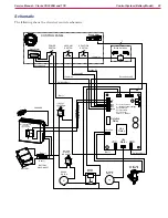


Control System (Corded Model)
18
Service Manual – Clarke CA30 20B and 17E
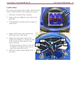
Control Panel
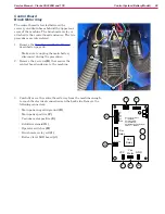
The control panel contains the machine control switches
and the DC power supply for the scrub relay. The
machine’s relays are located below the control panel.
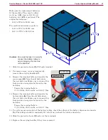
1. Make sure the machine is unplugged from power.
2. Remove the 4 screws
(B)
that secure the control
panel
(A)
.
3. Carefully lift the control panel up to expose the
wiring below.
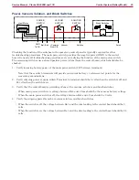
4. Remove the 2 AC input wires from the power
supply board.
•
The polarity of the wires is not critical to the
function of the power supply.
5. Unplug the DC output connector from the power
supply.
6. Using tape or similar label, make note of which
wiring bundles are connected to each of the 3
switches, and remove the 4 wires from each
switch.
•
During replacement, take care not to mix
the line and neutral wires on each side of
the switch. One side of the switch switches
the line-side and the other side switches the
neutral-side.
• Important:
Reversing these wires will result
in a direct short circuit of the 120-volt power.
B
A
24 VDC
Output
AC
Input
Neutral
Line


