Control System (Battery Model)
21
Service Manual – Clarke CA30 20B and 17E
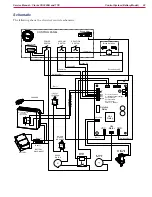
Battery Charger
The battery charger is semi-autonomous, and is always connected to the batteries unless the main battery
disconnect is unplugged. The charger is microprocessor-controlled to provide the optimal charge-curve to the
batteries depending on the battery type. The battery type, voltage, and max. current is determined by DIP
switches inside the charger. The charger also contains a small normally-closed relay that opens whenever
the charger is plugged in to building power. This relay serves to notify the machine’s control board that the
charger is plugged in and active, so that the control board can disable all machine functions while being
charged. When the charger is unplugged, the circuit is closed and the machine is enabled. When the charger
is plugged in, the circuit is open and the machine is disabled.
Vacuum Motor
The vacuum motor is controlled by a relay built in to the main control board. This relay switches the positive
power to the vacuum motor. This is fused through the same circuit breaker that provides power to the
control board. The negative power to the motor is unswitched and unfused from the battery.
Solution Solenoid
The solution solenoid is a 24-volt magnetically controlled valve that permits fluid to gravity-flow to the
scrub deck. Power to the solenoid comes from a relay on the machine control board. This relay switches the
negative power to the solenoid. The solution solenoid is active only when the solution switch is closed, and
at least one of the brush switches are closed. This causes the solution solenoid to be active only if the scrub
system is active. No solution will flow unless the brush is also active.
Brush Motor
The brush motor is controlled by a power relay adjacent to the control board. The positive power to the motor
passes through the second 30-amp circuit breaker. This circuit breaker serves only the brush motor. The
negative power to the motor is switched by the brush relay. Both positive and negative power to the relay
coil comes from the machine control board.
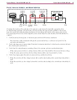
Vacuum, Solution, and Brush Switches
These switches are low-power control signals to the machine control board. They share a common positive
lead from the control board, and return that positive signal back to the control board when closed. The two
brush switches are in parallel, so that if either switch is closed, the circuit is completed.
Hour Meter
The hour meter is a simple clock that receives power from the main power switch, but is enabled only when
the scrub switches are closed.
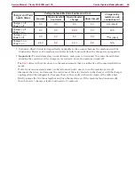
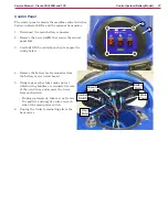
Battery Meter LEDs
The battery meter LEDs are controlled by the main control board based on the voltage of the battery. Each
successive LED turns on at a higher voltage level, depending on the position of the Wet/Gel DIP switch.
The operating voltage range of a wet battery is lower than a gel battery, so the LEDs will turn on at lower
voltage for wet versus gel batteries. When the battery is fully depleted, the 2 red LEDs will flash, and the
machine will shut down.


