


Scrub System
47
Service Manual – Clarke CA30 20B and 17E
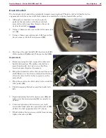
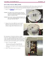
8. Disconnect the motor connector
(F)
and
solution solenoid connectors
(G)
. It is not
necessary to disconnect the vacuum motor
connector
(H)
, unless you need to service the
vacuum motor.
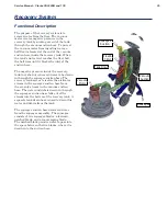
Replacement Notes
The replacement procedure is the reverse of the disassembly. When installed in the machine, the scrub deck
floats on two pivot brackets to conform to the slope of the floor. The left bracket rotates about its bolt. The
right bracket both rotates and slides vertically.
If you have difficulty holding these brackets in
the vertical position while lowering the machine,
use the following tips to help align them during
reassembly.
1. Move the scrub deck into position below the
machine. Verify the position by temporarily
lowering the machine to ensure it clears the
top of the brush motor. Raise the machine
back up.
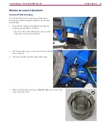
2. Route a piece of string or light rope
(L)
through one of the mounting holes in the
machine body
(K)
.
3. Route the string through the corresponding
hole
(J)
in the pivot bracket
(I)
. Note that the
string is routed from outside to inside through
the bracket.
4. Repeat the same for the second pivot bracket.
5. While lowering the machine body down over
the scrub deck, pull the string tight to keep
both pivot brackets vertical.
6. Loosely install the first screws and sleeves
(left & right), but do not fully tighten them
yet.
•
Because the right-hand bracket slides
vertically, you may need to push up slightly
from the bottom to align the hole.
7. Remove the string and install the remaining
two screws and sleeves.
8. After all 4 screws are loosely installed, tighten
them all down.
G
H
F
L
I
K
J


