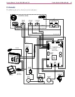
Control System (Battery Model)
25
Service Manual – Clarke CA30 20B and 17E
Power, Vacuum, Solution, and Brush Switches
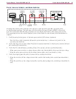
SOLUTION
SWITCH
POWER
SWITCH
VACUUM
SWITCH
Brush Switches
Scrub
Vacuum
+Common
From C.B.
Solution
Hour Meter
Bat+
Bat-
GND
To C.B.
Scrub
Checking the function of the switches in the operator’s control panel is typically required for other
troubleshooting procedures. The main power switch provides the negative power (GND) to the control
board. So nearly all troubleshooting procedures rely on verifying the function of the main power switch.
The remaining switches use a shared positive power (+Com) from the control board, which should also be
checked.
1. Verify incoming battery power at the main power switch (24V between terminals).
•
Note that these switch terminals will provide convenient b/- reference test points for the
remaining examinations.
2. Verify outgoing power at main switch. Terminal-to-terminal should be 0 volts when the switch is off, and
24 volts when the switch is on.
3. Verify that the control board is proCom at the vacuum, solution, and brush switches.
•
When main power switch is on, voltage between Bat- and +Com should be the same as battery voltage.
•
When the main power switch is off, the voltage between Bat- and +Com should be 0 volts.
4. Verify the outgoing power from the vacuum, solution, and brush switches.
•
When the switch is off, the voltage between Bat- and the wire leading to the control board should be 0
volts.
•
When the switch is on, the voltage between Bat- and the wire leading to the control board should be 24
volts.


