


Control System (Corded Model)
13
Service Manual – Clarke CA30 20B and 17E
Schematic
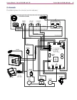
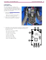
The following shows the electrical controls schematic. Each of the functions are further described in the
subsequent sections.
SOLUTION
SWITCH
POWER
SWITCH
VACUUM
SWITCH
24V DC
Power Supply
~
~
Brush Switches
+
-
24V
DC
8
7
SOLUTION
SOLENOID
Scrub Control
Relay
5
4
2
1
START
RUN
BRUSH
MOTOR
MOTOR START
RELAY
CONTROL PANEL
Coil
Main Power
The main machine power comes from 120-volt AC mains power. This first passes through a resettable circuit
breaker for circuit overload protection. All power to the remainder of the machine passes through the main
power switch in the control panel, which switches both line and neutral conductors to the rest of the system.
All downstream functions are in series with this circuit breaker and switch.
Vacuum Motor
The vacuum motor receives its power from the main power switch. It too switches both line and neutral
conductors. From here, the line-side passes through a resettable circuit breaker to protect the motor, and
then directly to the motor. The vacuum motor is a “universal motor”, which means it uses internal carbon
brushes for mechanical commutation of the winding polarity.


