


•
DC power cable lugs
•
Crimping tool and lug-specific die
•
3/8-inch ratchet wrench with 7/16-pt. socket
•
Multimeter
•
Torque wrench with torque value rated up to 55 in-lb (6.2 N-m)
•
Terminal block cover
•
Torque screwdriver with Number-1 Phillips 8-inch shank, and a torque rating of 5 to 7 in-lb (0.56 to
0.79 N-m)
Steps
To connect the DC input power cables, follow these steps:
Step 1
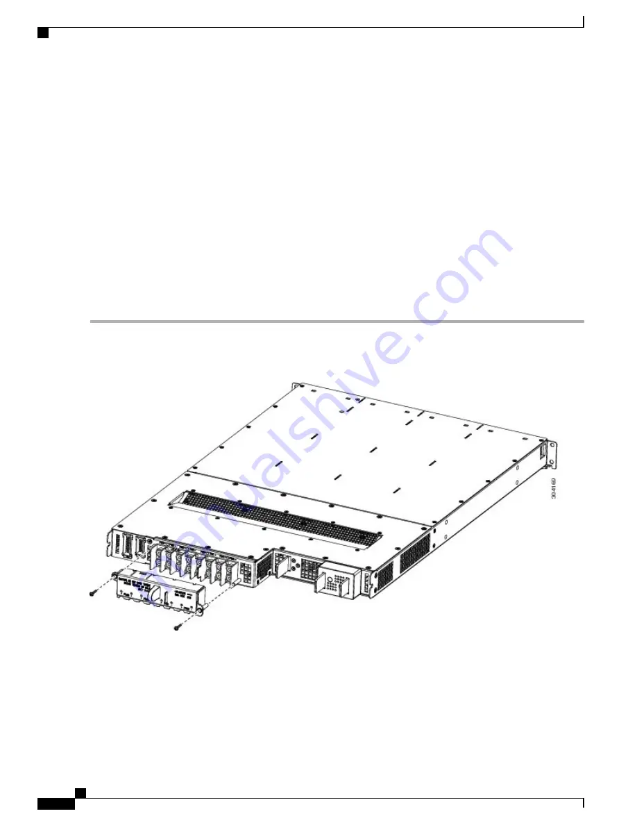
Remove any DC terminal block covers, if installed.
Figure 38: DC Terminal Block Cover Installed on Rear of the Power Tray
Step 2
Verify the following resistance values:
•
The resistance between the positive and negative power terminal studs of each input must be greater than 90 kohm.
•
The resistance between each positive terminal stud and bare metal surface on the power tray must be greater that
10 Mohm.
Cisco Network Convergence System 6000 Fabric Card Chassis Hardware Installation Guide
56
Installing the Power Components
Installing DC Input Power Cables


