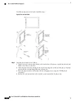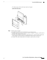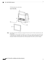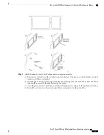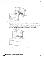
For cables that terminate outside of the bracket, use the cable-access openings in the bottom of the bracket to
position the power cord and any other cable that does not terminate in the wall behind the bracket. The phone
and wall bracket openings together form circular openings with room for one cable per opening.
Step 5
Proceed to
Adjust the Handset Rest, on page 116
.
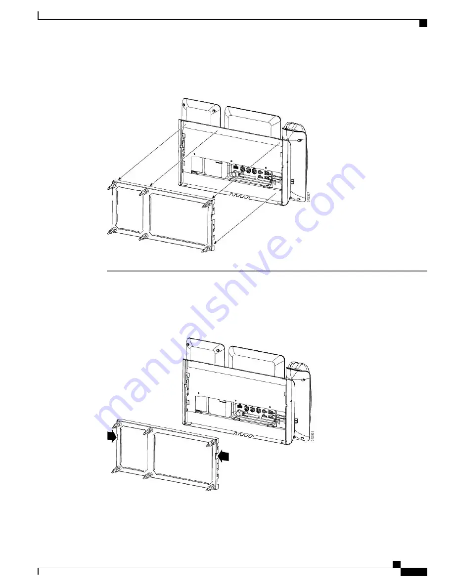
Remove the Phone and Key Expansion Module from the Non-Lockable Wall Mount
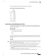
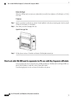
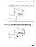
The wall bracket has two tabs that lock the kit together. Use the following illustration to locate the tabs.
Cisco IP Phone 8800 Series Multiplatform Phones Administration Guide
115
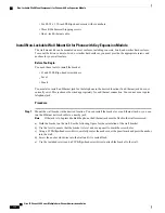
Non-Lockable Wall Mount Components for Phone with Key Expansion Module
Содержание 8851
Страница 23: ...P A R T I About the Cisco IP Phone Technical Details page 9 Cisco IP Phone Hardware page 21 ...
Страница 24: ......
Страница 36: ...Cisco IP Phone 8800 Series Multiplatform Phones Administration Guide 20 USB Port Information ...
Страница 48: ......
Страница 96: ...Cisco IP Phone 8800 Series Multiplatform Phones Administration Guide 80 Administrator and User Accounts ...
Страница 98: ......
Страница 118: ...Cisco IP Phone 8800 Series Multiplatform Phones Administration Guide 102 Troubleshoot the Key Expansion Module ...
Страница 134: ...Cisco IP Phone 8800 Series Multiplatform Phones Administration Guide 118 Adjust the Handset Rest ...
Страница 136: ......
Страница 142: ...Cisco IP Phone 8800 Series Multiplatform Phones Administration Guide 126 Documentation Support and Security Guidelines ...
Страница 168: ...Cisco IP Phone 8800 Series Multiplatform Phones Administration Guide 152 XML Services ...
Страница 204: ...Cisco IP Phone 8800 Series Multiplatform Phones Administration Guide 188 Capture Packets ...
Страница 208: ...Cisco IP Phone 8800 Series Multiplatform Phones Administration Guide 192 Configure the XML Directory Service ...
Страница 210: ......
Страница 292: ...Cisco IP Phone 8800 Series Multiplatform Phones Administration Guide 276 Cisco IP Phone Web Page ...

