3-11
Cisco ASA 5580 Series Adaptive Security Appliance Hardware Installation Guide
OL-12920-01
Chapter 3 Installing the ASA 5580
Connecting Interface Cables
b.
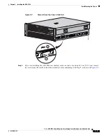
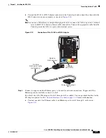
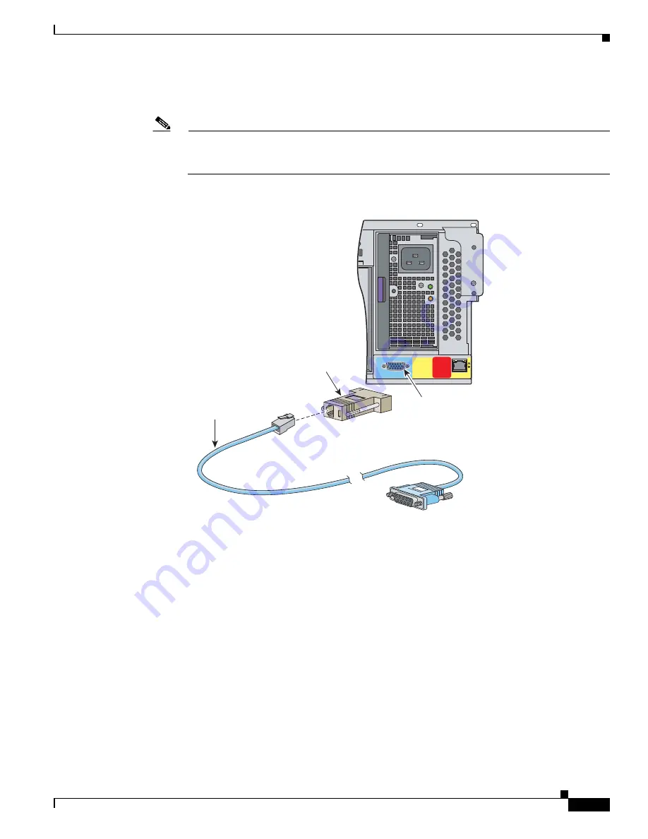
Connect the RJ-45 to a DB-9 adapter connector to the Console port and connect the other end to the
DB-9 connector on your computer, as shown in
Figure 3-10
.
Note
You can use a 180/rollover or straight-through patch cable to connect the ASA to a port on a terminal
server with RJ-45 or hydra cable assembly connections. Connect the appropriate cable from the
Console port on the ASA to a port on the terminal server.
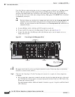
Figure 3-10
Connection of the RJ-45 to a DB-9 Adapter
Step 4
Connect to copper and fiber Ethernet ports to be used for network connections. Copper and Fiber
Ethernet ports are available in slots 3 to slot 8.
By default, the ASA 5580 ships with slot 3 through slot 8 available. You can purchase bundles for the
I/O adapter options.
See the
“Network Interfaces” section on page 1-10
for more information.
a.
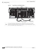
Connect one end of an Ethernet cable to an Ethernet port in slots 3 through 8, as shown in
Figure 3-11
.
Comp
u
ter
s
eri
a
l port
DB-9
250084
1
PS1
Reserved
for
Future Use
CONSOLE
MGMT 0/0
RJ-45 to
DB-9
s
eri
a
l c
a
ble
(n
u
ll-modem)
Con
s
ole
port (DB-9)
RJ-45 to
DB-9
a
d
a
pter
Содержание 5580-40 - ASA Firewall Edition
Страница 6: ...Contents vi Cisco ASA 5580 Adaptive Security Appliance Hardware Maintenance Guide OL 12920 01 ...
Страница 12: ...xii Cisco ASA 5580 Series Adaptive Security Appliance Hardware Installation Guide OL 12920 01 About This Guide ...
Страница 84: ...Index IN 4 Cisco ASA 5580 Adaptive Security Appliance Hardware Maintenance Guide OL 12920 01 ...

