4-4
Cisco ASA 5580 Series Adaptive Security Appliance Hardware Installation Guide
OL-12920-01
Chapter 4 Maintenance and Upgrade Procedures
Accessing the Diagnostic Panel
Replacing the Chassis Cover
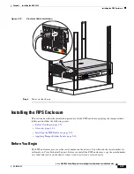
To replace the chassis cover, perform the following steps:
Step 1
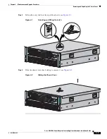
Position the cover on top of the chassis and slide it on. Push down on the cover latch to lock it into place.
Note
Make sure the chassis cover is securely locked into place before powering on the ASA.
Step 2
Reinstall the ASA in a rack, on a desktop, or on a table, or extend it back into the rack.
Accessing the Diagnostic Panel
Note
When you remove the chassis cover to view the Diagnostic Panel, leave the ASA powered on. Powering
off the ASA clears the Diagnostic Panel indicators.
To access the Diagnostic Panel, perform the following steps:
Step 1
Extend the ASA from the rack.
Step 2
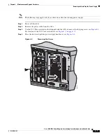
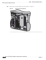
Remove the chassis cover.
For more information, see
Removing the Chassis Cover, page 4-2
.
Step 3
Locate the Diagnostic Panel (see
Figure 1-5 on page 1-9
)
For information on what internal health information each indicator displays, see the
“Figure 1-5Diagnostic Panel” section on page 1-9
. Follow the instructions in this chapter to remove and
install failed components. For aid in troubleshooting, use the internal health indicators information when
contacting TAC.
Removing and Installing the Interface Cards
The ASA 5580 has nine expansion card slots. For detailed information about network interfaces and
available cards, see the
“Network Interfaces” section on page 1-10
.
Содержание 5580-40 - ASA Firewall Edition
Страница 6: ...Contents vi Cisco ASA 5580 Adaptive Security Appliance Hardware Maintenance Guide OL 12920 01 ...
Страница 12: ...xii Cisco ASA 5580 Series Adaptive Security Appliance Hardware Installation Guide OL 12920 01 About This Guide ...
Страница 84: ...Index IN 4 Cisco ASA 5580 Adaptive Security Appliance Hardware Maintenance Guide OL 12920 01 ...

