background image


4-25

Cisco ASA 5580 Series Adaptive Security Appliance Hardware Installation Guide

OL-12920-01

Chapter 4      Maintenance and Upgrade Procedures

  Troubleshooting Loose Connections

  •

Make sure each device is properly seated.

  •

If a device has latches, make sure they are completely closed and locked.

  •

Check any interlock or interconnect indicators that indicate a component is not connected properly.

If problems continue, remove and reinstall each device, checking the connectors and sockets for bent 
pins or other damage.

Содержание 5580-40 - ASA Firewall Edition

Страница 1: ...arters Cisco Systems Inc 170 West Tasman Drive San Jose CA 95134 1706 USA http www cisco com Tel 408 526 4000 800 553 NETS 6387 Fax 408 527 0883 Cisco ASA 5580 Hardware Installation Guide Text Part Number OL 12920 01 ...

Страница 2: ...ulations and you may be required to correct any interference to radio or television communications at your own expense You can determine whether your equipment is causing interference by turning it off If the interference stops it was probably caused by the Cisco equipment or one of its peripheral devices If the equipment causes interference to radio or television reception try to correct the inte...

Страница 3: ... 4 Rear Panel Overview 1 5 Ethernet Port Activity Indicators 1 6 Power Supply Indicators 1 7 Internal Components 1 8 Diagnostic Panel 1 9 Network Interfaces 1 10 Built In Management Interfaces 1 10 Expansion Slots and PCI Buses 1 10 PCI Adapters 1 11 4 Port Gigabit Ethernet Copper PCI Adapter 1 11 4 Port Gigabit Ethernet Fiber PCI Adapter 1 11 2 Port 10 Gigabit Ethernet Fiber PCI Adapter 1 11 I O ...

Страница 4: ...ssembly 3 18 Applying Tamper Evident Labels 3 19 C H A P T E R 4 Maintenance and Upgrade Procedures 4 1 Removing and Replacing the Chassis Cover 4 1 Removing the Chassis Cover 4 2 Replacing the Chassis Cover 4 4 Accessing the Diagnostic Panel 4 4 Removing and Installing the Interface Cards 4 4 Removing the Interface Cards 4 5 Installing an Interface Cards 4 6 Removing and Installing the Power Supp...

Страница 5: ... 5580 Adaptive Security Appliance Hardware Maintenance Guide OL 12920 01 A P P E N D I X A Cable Pinouts A 1 10 100 1000BaseT Ports A 1 Console Port RJ 45 A 2 Console RJ 45 to DB 9 Adapter A 3 SFP Fiber Ports A 4 I N D E X ...

Страница 6: ...Contents vi Cisco ASA 5580 Adaptive Security Appliance Hardware Maintenance Guide OL 12920 01 ...

Страница 7: ...ho install firewalls Installation Warnings Be sure to read the Regulatory Compliance and Safety Information for the Cisco ASA 5580 document that accompanied this device before installing the chassis This document contains important safety information This section includes the following warnings AC Power Disconnection Warning page viii Jewelry Removal Warning page viii Wrist Strap Warning page viii...

Страница 8: ...units Statement 246 Jewelry Removal Warning Warning Before working on equipment that is connected to power lines remove jewelry including rings necklaces and watches Metal objects will heat up when connected to power and ground and can cause serious burns or weld the metal object to the terminals Statement 43 Wrist Strap Warning Warning During this procedure wear grounding wrist straps to avoid ES...

Страница 9: ...ning To avoid electric shock do not connect safety extra low voltage SELV circuits to telephone network voltage TNV circuits LAN ports contain SELV circuits and WAN ports contain TNV circuits Some LAN and WAN ports both use RJ 45 connectors Use caution when connecting cables Statement 1021 Ground Conductor Warning Warning This equipment must be grounded Never defeat the ground conductor or operate...

Страница 10: ...he risk of electric shock when servicing a unit disconnect the power cord of the power strip that the unit is plugged into Statement 137 Circuit Breaker 15A Warning Warning This product relies on the building s installation for short circuit overcurrent protection Ensure that a fuse or circuit breaker no larger than 120 VAC 15A U S 240 VAC 10A international is used on the phase conductors all curr...

Страница 11: ...ompliance and Safety Information for the Cisco ASA 5580 document that accompanied the product This document describes the international agency compliance and safety information for the adaptive security appliance It also includes translations of the safety warnings Obtaining Documentation and Submitting a Service Request For information on obtaining documentation submitting a service request and g...

Страница 12: ...xii Cisco ASA 5580 Series Adaptive Security Appliance Hardware Installation Guide OL 12920 01 About This Guide ...

Страница 13: ...ice this equipment Statement 49 Caution Read the safety warnings in the Regulatory Compliance and Safety Information for the Cisco ASA 5580 and follow proper safety procedures when performing these steps This chapter describes the product and the memory requirements and includes the following topics Package Contents page 1 2 Model Variants page 1 2 Front and Rear Panel Overview page 1 3 Internal C...

Страница 14: ...acket Model Variants The Cisco ASA 5580 comes in two models ASA 5580 20 Includes 2 processors ASA 5580 40 Includes 4 processors The 5580 40 also includes more DRAM by default 1 ASA 5580 Series Chassis 2 RJ 45 to DB 9 Adapter 3 2 Yellow Ethernet Cables 4 Documentationt and Software CD 5 Blue Console Cable PC Terminal Adapter 1 2 3 4 5 6 7 8 Cisco ASA 5580 SERIES Adaptive Security Appliance UID SY S...

Страница 15: ... 40 section on page 4 13 Front and Rear Panel Overview This section describes the front and rear panels and includes the following topics Front Panel page 1 3 Rear Panel page 1 4 Front Panel Figure 1 1 shows the front panel Figure 1 1 Front Panel 1 Active LED 2 System LED 3 Power Status LED 4 Management 0 0 LED 5 Management 0 1 LED 6 Power 1 2 3 4 5 6 7 8 241233 Cisco IPS 4270 SERIES Intrusion Pre...

Страница 16: ...e off pushing the button lights it Pushing the button again will cause it to turn off again Indicates the Active and Standby Failover status of the chassis On Failover active Off Standby Status System indicator Indicates internal system health Green System on Flashing amber System health degraded Flashing red System health critical Off System off Power status indicator Indicates the power supply s...

Страница 17: ...anel For more information about the network interfaces see the Network Interfaces section on page 1 10 1 Power supply 2 Interface expansion slots 3 Power supply 4 T 15 Torx screwdriver 5 USB ports 6 Reserved slot 7 Example of a populated slot 8 Reserved slot 9 Console port 10 Management ports 1 2 3 4 5 6 7 8 9 PCI E x4 PCI E x8 PCI E x4 PCI E x8 PCI E x4 PCI X 100 MHz PS2 PS1 UID MGMT0 0 MGMT0 1 C...

Страница 18: ...ce card port in a 10 Gigabit Ethernet Fiber interface card or a port in a Gigabit Ethernet Fiber interface card 1 Power indicator 2 Link indicator 3 Activity indicator 1 2 3 4 5 6 7 8 9 PCI E x4 PCI E x8 PCI E x4 PCI E x8 PCI E x4 PCI X 100 MHz PS2 PS1 UID MGMT0 0 MGMT0 1 241230 CONSOLE 1 2 3 Table 1 2 Ethernet Port Indicators Indicator Description Gigabit Ethernet Green top link to network Flashi...

Страница 19: ...verview Power Supply Indicators Table 1 3 describes the power supply indicators Table 1 3 Power Supply Indicators Fail Indicator 1 Amber Power Indicator 2 Green Description Off Off No AC power to any power supply Flashing Off Power supply failure over current On Off No AC power to this power supply Off Flashing AC power present Standby mode Off On Normal ...

Страница 20: ...uide OL 12920 01 Chapter 1 Introduction to the ASA 5580 Internal Components Internal Components Figure 1 4 shows the internal components of the ASA 5580 Figure 1 4 Internal Components 1 3 Power supply 4 5 7 Fans 2 Interface expansion slots 6 Diagnostic panel 241974 1 3 5 7 6 4 2 ...

Страница 21: ...s see the Internal Components section on page 1 8 For information on how to access the Diagnostic Panel see the Accessing the Diagnostic Panel section on page 4 4 Figure 1 5 Diagnostic Panel Table 1 4 lists the indicators that display health status for each component PROC1 FAN5 FAN6 FAN3 FAN4 FAN1 FAN2 PROC2 PROC3 PROC4 POWER FAULT PS1 PS2 CPU BD I O BD NMI INTERLOCK ERROR CPU BD 9A 10A 11B 12B 13...

Страница 22: ...ble of passing through traffic see the interfaces chapter in the configuration guide However the management only interfaces have not been optimized to pass data traffic and will not perform as well as the interfaces on the adapters Expansion Slots and PCI Buses The ASA 5580 has nine expansion slots Slots 3 through 8 For supported PCI Express network interface adapters Slots 1 2 and 9 Reserved Slot...

Страница 23: ...X fiber interfaces These interfaces require a multi mode fiber cable with an LC connector to connect to the SX interface of the sensor Optimizing Performance The Gigabit Ethernet Fiber PCI adapter with SR optics has a distance capability of 300 meters The adapters are designed to support short distances over deployed multi mode fiber cabling with a range of between 26 metres 85 ft and 82 metres 27...

Страница 24: ...nce To maximize traffic throughput see the following best practices in order of importance 1 Have equal amounts of traffic on both I O bridges See the I O Bridges section on page 1 12 for more information about which slots are connected to each bridge Because of the way the I O bridges connect to the 4 CPU array having equal amounts of traffic on the two I O bridges means less latency when the tra...

Страница 25: ...so includes the Auto MDI MDIX feature Auto MDI MDIX eliminates the need for crossover cabling by performing an internal crossover when a straight cable is detected during the auto negotiation phase Either the speed or duplex must be set to auto negotiate to enable Auto MDI MDIX for the interface If you explicitly set both the speed and duplex to a fixed value thus disabling auto negotiation for bo...

Страница 26: ...r flash memory will fail Rated input power 1161W 100 VAC 1598W 200 VAC Rated input current 12A 100 VAC 8A 200 VAC Maximum heat dissipation 3960 BTU hr 100 VAC 5450 BTU hr 200 VAC Power supply output 910 W low line 1300 W high line Environment Temperature Operating 50 to 95 F 10 to 35 C 2 Nonoperating 40 F to 158 F 40 C to 70 C Maximum wet bulb temperature 82 4 F 28 C Relative humidity noncondensin...

Страница 27: ...ecial tools and does not create any radio frequency leaks The safety guidelines are as follows Keep the chassis area clear and dust free before during and after installation Keep tools away from walk areas where you and others could fall over them Do not wear loose clothing or jewelry such as earrings bracelets or chains that could get caught in the chassis Wear safety glasses if you are working u...

Страница 28: ...rmation for the Cisco ASA 5580 document The ASA model equipped with AC input power supplies are shipped with a 3 wire electrical cord with a grounding type plug that fits only a grounding type power outlet Do not circumvent this safety feature Equipment grounding should comply with local and national electrical codes Preventing Electrostatic Discharge Damage Electrostatic discharge ESD can damage ...

Страница 29: ...es without adequate circulation Ensure that the room in which you operate your system has adequate air circulation Always follow the ESD prevention procedures described previously to avoid damage to equipment Damage from static discharge can cause immediate or intermittent equipment failure Ensure that the chassis top panel is secure The chassis is designed to allow cooling air to flow effectively...

Страница 30: ...n to provide cooling air When mounting a chassis in an open rack ensure that the rack frame does not block the intake or exhaust ports If the chassis is installed on slides check the position of the chassis when it is seated all the way into the rack In an enclosed rack with a ventilation fan in the top excessive heat generated by equipment near the bottom of the rack can be drawn upward and into ...

Страница 31: ... adequate ventilation An enclosed rack should never be overcrowded Make sure that the rack is not congested because each unit generates heat When mounting a device in an open rack make sure that the rack frame does not block the intake or exhaust ports If the rack contains only one unit mount the unit at the bottom of the rack If the rack is partially filled load the rack from the bottom to the to...

Страница 32: ...n the rack Statement 1006 This procedure requires two or more people to position the ASA 5580 on the slide assemblies before pushing it in to the rack To install the ASA 5580 in the rack perform the following steps Step 1 Attach the chassis side rail to the ASA 5580 by aligning the chassis rail to the stud on the ASA 5580 pressing the chassis side rail in to the stud and then sliding the chassis s...

Страница 33: ... 3 2 Removal from the Chassis Side Rail Step 4 If you are installing the ASA 5580 in a shallow rack one that is less than 28 5 in 72 39 cm remove the screw from the inside of the slide assembly before continuing with Step 5 as shown in Figure 3 3 1 2 3 4 5 6 7 8 Cisco IPS 4270 SERIES Intrusion Prevention Sensor UID SY ST EM PW RST AT US MGMT0 MGMT1 1 2 250120 ...

Страница 34: ... Cisco ASA 5580 Series Adaptive Security Appliance Hardware Installation Guide OL 12920 01 Chapter 3 Installing the ASA 5580 Rack Mounting the Chassis Figure 3 3 Screw Inside the Slide Assembly 201991 28 5 ...

Страница 35: ... Attach the slide assemblies to the rack as shown in Figure 3 4 For round and square hole racks a Line up the studs on the slide assembly with the holes on the inside of the rack and snap into place b Adjust the slide assembly lengthwise to fit the rack The spring latch locks the slide assembly into position Figure 3 4 Slide Assembly Attachment 1 1 2 3 201992 ...

Страница 36: ...o release the slide assembly if you need to reposition it For threaded hole racks a Remove the eight round or square hole studs on each slide assembly using a standard screwdriver as shown in Figure 3 5 Note You may need a pair of pliers to hold the retaining nut Figure 3 5 Attachment in Threaded Hole Racks b Line up the bracket on the slide assembly with the rack holes install two screws top and ...

Страница 37: ...nce Hardware Installation Guide OL 12920 01 Chapter 3 Installing the ASA 5580 Rack Mounting the Chassis Figure 3 6 Lining up the Bracket c Repeat for each slide assembly Step 6 Extend the slide assemblies out of the rack as shown in Figure 3 7 1 201994 ...

Страница 38: ...the ASA 5580 with the slide assembly on both sides of the rack release the blue slide tab by either pulling the tab forward or pushing the tab back and carefully push the ASA 5580 in to place as shown in Figure 3 8 Warning When installing a ASA 5580 in an empty rack you must support the ASA 5580 from the front until the blue slide tabs are activated and the ASA 5580 is pushed completely in to the ...

Страница 39: ...or down can damage the slide rails Connecting Interface Cables This section describes how to connect the appropriate cables to the Console Management copper Ethernet and fiber Ethernet ports To connect cables to the network interfaces perform the following steps Step 1 Place the chassis on a flat stable surface or in a rack if you are rack mounting it Step 2 Connect to the Management port 1 2 3 4 ...

Страница 40: ...cable which has an RJ 45 connector on each end b Connect one RJ 45 connector to the Management 0 0 port as shown in Figure 3 9 c Connect the other end of the Ethernet cable to the Ethernet port on your computer or to your management network Figure 3 9 Connecting to the Management Port Caution Management and console ports are privileged administrative ports Connecting them to an untrusted network c...

Страница 41: ... Console port on the ASA to a port on the terminal server Figure 3 10 Connection of the RJ 45 to a DB 9 Adapter Step 4 Connect to copper and fiber Ethernet ports to be used for network connections Copper and Fiber Ethernet ports are available in slots 3 to slot 8 By default the ASA 5580 ships with slot 3 through slot 8 available You can purchase bundles for the I O adapter options See the Network ...

Страница 42: ...t cables to a network device such as a router or switch Step 5 Install the electrical cables at the back of the ASA Attach the power cables and plug them in to a power source we recommend a UPS as shown in Figure 3 12 1 1 2 3 4 5 6 7 8 9 PCI E x4 PCI E x8 PCI E x4 PCI E x8 PCI E x4 PCI X 100 MHz PS2 PS1 UID CONSOLE MGMT0 0 241234 Reserved Reserved Interface expansion slots MGMT0 1 Multi mode fiber...

Страница 43: ...3 13 Overview page 3 14 Installing the FIPS Enclosure page 3 15 Applying Tamper Evident Labels page 3 19 Before You Begin The FIPS enclosures may cover the serial number on the chassis You will need the serial number for calls made to Cisco Technical Support Before you install the FIPS enclosures copy the serial number on a label and stick it on the chassis where it can be retrieved or viewed easi...

Страница 44: ...are Installation Guide OL 12920 01 Chapter 3 Installing the ASA 5580 Installing the FIPS Enclosure Overview Figure 13 shows the front shield assembly of the FIPS enclosure for the ASA 5580 Figure 13 Front Shield Assembly 1 Self adhesive tape with liner 279250 1 ...

Страница 45: ...nt Shield Assembly page 3 15 Installing the Rear Shield Assembly page 3 18 Note The maximum operating temperature for the Cisco ASA 5580 with the shields installed should be 32C Installing the Front Shield Assembly To install the front shield assembly you must first pull out the processor module from the chassis To pull out the processor module perform the following steps Step 1 Power off the ASA ...

Страница 46: ...Figure 15 Releasing the Latch and Lowering the Handle Step 5 Remove the five screws from the top and four screws on the sides of the front shield assembly Keep the screws in a secure place for later use The front shield assembly consists of a front surround panel that has double sided tape and a front panel See Figure 16 Figure 16 Front Surround Panel and the Front Panel Step 6 Clean the chassis o...

Страница 47: ...t Surround Panel on the Module Step 8 Remove the tape backing from the self adhesive tape Step 9 Press down the self adhesive tape to make sure the front surround panel is firmly stuck to the chassis Step 10 Push the module back into the chassis and use the handle to lock the module into place See Figure 18 Figure 18 Locking the Module into Place 1 Roller balls 1 2 3 4 5 6 7 8 279326 UID SYSTEM PW...

Страница 48: ... Figure 19 Figure 19 Installing the Front Panel to the Front Surround Panel Installing the Rear Shield Assembly To install the rear shield assembly perform the following steps Step 1 Position the rear shield assembly on the rear of the chassis and align the rear shield panel holes with the holes on the rear of the chassis Step 2 Secure the shield into place using the screws provided in the kit See...

Страница 49: ...ease dirt or oil before applying the tamper evident labels Alcohol based cleaning pads are recommended for this purpose Step 1 Apply seven tamper evident labels to the front of the chassis as shown in Figure 21 Figure 21 ASA 5580 Tamper Evident Label Placement Step 2 Apply six tamper evident labels to the back of the chassis as shown in Figure 22 Figure 22 ASA 5580 Tamper Evident Label Placement 1...

Страница 50: ... 5580 Installing the FIPS Enclosure Step 3 Apply two tamper evident labels to the left of the chassis as shown in Figure 23 Figure 23 ASA 5580 Tamper Evident Label Placement Step 4 Apply one tamper evident label to the right of the chassis as shown in Figure 24 Figure 24 ASA 5580 Tamper Evident Label Placement 279324 279325 ...

Страница 51: ... on the ASA chassis is specific to the ASA and must only be upgraded under instructions from Cisco with BIOS files obtained from the Cisco website Installing a non Cisco or third party BIOS on the ASA voids the warranty Removing and Replacing the Chassis Cover This section describes how to remove and replace the chassis cover from the ASA This section includes the following topics Removing the Cha...

Страница 52: ...eading the safety warnings in Regulatory Compliance and Safety Information for the Cisco ASA 5580 Caution Do not operate the ASA for long periods with the chassis cover open or removed Operating it in this manner results in improper airflow and improper cooling that can lead to thermal damage Removing the Chassis Cover To remove the chassis cover perform the following steps Note Removing the chass...

Страница 53: ...e top of the chassis see Figure 4 1 Figure 4 1 Unlocking and Lifting the Latch Step 4 Slide the chassis cover back and up to remove it see Figure 4 2 Figure 4 2 Sliding the Chassis Cover 241967 1 2 3 4 5 6 7 8 Cisco ASA 5580 SERIES Adaptive Security Appliance UID SYSTE M PWRSTATU S MGMT0 MGMT1 1 2 3 4 5 6 7 8 241968 1 2 3 4 5 6 7 8 Cisco ASA 5580 SERIES Adaptive Security Appliance UID SYSTE M PWRS...

Страница 54: ...anel leave the ASA powered on Powering off the ASA clears the Diagnostic Panel indicators To access the Diagnostic Panel perform the following steps Step 1 Extend the ASA from the rack Step 2 Remove the chassis cover For more information see Removing the Chassis Cover page 4 2 Step 3 Locate the Diagnostic Panel see Figure 1 5 on page 1 9 For information on what internal health information each ind...

Страница 55: ...eps Step 1 Power off the ASA Step 2 Remove the power cables from the ASA Step 3 If rack mounted extend the ASA from the rack Step 4 Make sure the ASA is in an ESD controlled environment For more information see the Preventing Electrostatic Discharge Damage section on page 2 2 Step 5 Remove the chassis cover For more information see the Removing the Chassis Cover section on page 4 2 Step 6 To unloc...

Страница 56: ...y appliance Step 5 Power on the Cisco ASA 5580 series adaptive security appliance Removing and Installing the Power Supply For information on power supply considerations including environmental operating ranges and power requirements see table 8 at the following url http www cisco com en US prod collateral vpndevc ps6032 ps6094 ps6120 product_data_sheet0900a ecd802930c5 html Note Make sure the two...

Страница 57: ...functioning power supply Step 1 Power off the ASA Step 2 Remove the power cable from the ASA Step 3 Use the T 15 Torx screwdriver that shipped with the ASA to remove the shipping screw see Figure 4 4 For location of the T 15 Torx screwdriver see Figure 1 2 on page 1 5 Step 4 Press the latch and pull the power supply handle out see Figure 4 4 Figure 4 4 Removing the Screw 1 2 3 4 PCI E x4 PCI X 100...

Страница 58: ...0 01 Chapter 4 Maintenance and Upgrade Procedures Removing and Installing the Power Supply Step 5 Remove the power supply by pulling it away from the chassis see Figure 4 5 Figure 4 5 Pulling the Power Supply Handle 1 2 3 4 PCI E x4 PCI X 100 MHz CONSOLE MGMT 0 0 CONSOLE MGMT 0 1 PS1 241971 ...

Страница 59: ...pgrade Procedures Removing and Installing the Power Supply Installing the Power Supply To install the power supply in the ASA perform the following steps Step 1 Align and push the power supply into place see Figure 4 6 Figure 4 6 Pushing the Power Supply 1 2 3 4 PCI E x4 PCI X 100 MHz CONSOLE MGMT 0 0 MGMT 0 1 PS1 241972 ...

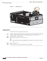
Страница 60: ...nel health indicators are green Step 5 Power on the ASA Removing and Installing Fans There are six fans in the Cisco ASA 5580 series adaptive security appliance For the fan locations see Figure 1 4 on page 1 8 The Cisco ASA 5580 series adaptive security appliance supports redundant hot pluggable fans in a 5 1 configuration to provide proper airflow This section describes how to install and remove ...

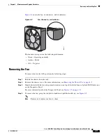
Страница 61: ...power Removing the Fan To remove fans in the ASA perform the following steps Step 1 Extend the chassis from the rack Step 2 Remove the chassis cover For more information see Removing the Chassis Cover page 4 2 Step 3 Identify the failed fan by locating an amber indicator on top of the failed fan or a lighted FAN X indicator on the Diagnostic Panel For more information about the Diagnostic Panel se...

Страница 62: ... fan indicator lines up with the connection on the motherboard for the location of the connector see Figure 4 8 Step 2 Push down until the fan clicks into place Step 3 Check to make sure the indicator on each fan is green Note If the front panel internal system health indicator is not green after you install a fan reseat the fan Step 4 Replace the chassis cover Step 5 Slide the ASA back in to the ...

Страница 63: ... a Product Activation Key PAK when the order is fulfilled Per the enclosed instructions you should visit http www cisco com go license where you will be prompted to enter your contact information and PAK number along with the serial number of your module The software on the Content Security Edition module will be enabled for the new user count and or Plus functionality automatically and transparen...

Страница 64: ...dures Upgrading the ASA 5580 20 to an ASA 5580 40 Figure 4 10 Releasing the Latch and Lowering the Handle Step 4 Firmly holding the module press the release buttons and pull the module out of the ASA see Figure 4 11 Figure 4 11 Release Button Location Step 5 Release the latch and open the cover 242070 1 Release buttons 2 Module 242071 ...

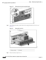
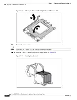
Страница 65: ...equipment multiple processors installed in the ASA must have the same part number Caution Processor and processor power module sockets 1 and 2 must be populated at all times or the ASA will not function properly Caution To help avoid damage to the processor and system board use the processor installation tool to install the new processor Caution Use caution when installing the processor memory mod...

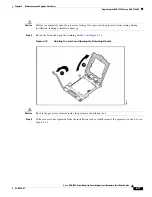
Страница 66: ...A 5580 20 to an ASA 5580 40 Figure 4 12 Opening the Heatsink Bracket Caution The pins on the processor socket are very fragile Any damage to them may require replacing the system board Step 3 Remove the processor socket protective cover see Figure 4 13 Retain the cover for future use Figure 4 13 Removing the Processor Socket Protective Cover 242073 242074 ...

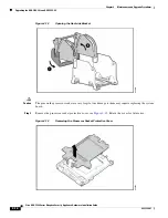
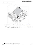
Страница 67: ...ing lever prevents the processor from seating during installation leading to hardware damage Step 4 Rotate the latch and open the retaining bracket see Figure 4 14 Figure 4 14 Rotating the Latch and Opening the Retaining Bracket Caution Be sure the processor remains inside the processor installation tool Step 5 If the processor has separated from the installation tool carefully reinsert the proces...

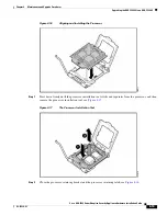
Страница 68: ...e ASA 5580 20 to an ASA 5580 40 Figure 4 15 Reinsert the Processor in the Tool Step 6 Align the processor installation tool with the socket and install the processor see Figure 4 16 Caution The processor is designed to fit one way into the socket Use the alignment guides on the processor and socket to properly align the processor with the socket 242076 ...

Страница 69: ...5580 40 Figure 4 16 Aligning and Installing the Processor Step 7 Press down firmly until the processor installation tool clicks and separates from the processor and then remove the processor installation tool see Figure 4 17 Figure 4 17 The Processor Installation Tool Step 8 Close the processor retaining bracket and the processor retaining latch see Figure 4 18 242077 242078 ...

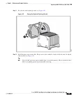
Страница 70: ...ng the ASA 5580 20 to an ASA 5580 40 Figure 4 18 Closing the Processor Retaining Bracket and Retaining Latch Step 9 Remove the heatsink cover Caution After the cover is removed do not touch the thermal interface media Step 10 Install the heatsink you must press hard to clamp it down see Figure 4 19 Figure 4 19 Installing the Heatsink 242079 242080 ...

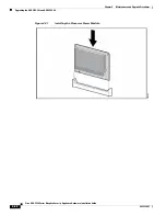
Страница 71: ...e the heatsink retaining bracket see Figure 4 20 Figure 4 20 Closing the Heatsink Retaining Bracket Step 12 Install the processor power module The processor power module is keyed and the key must be aligned when installed see Figure 4 21 Note Always install a processor power module when you install a processor The system fails to boot if the corresponding processor power module is missing 242081 ...

Страница 72: ... Series Adaptive Security Appliance Hardware Installation Guide OL 12920 01 Chapter 4 Maintenance and Upgrade Procedures Upgrading the ASA 5580 20 to an ASA 5580 40 Figure 4 21 Installing the Processor Power Module 242082 ...

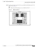
Страница 73: ...e and Upgrade Procedures Upgrading the ASA 5580 20 to an ASA 5580 40 Step 13 Install the memory module into the ASA The four memory modules should be installed in slots 17I 18I 25M and 26M see Figure 4 22 Note Memory location before upgrading are 1A 2A 3B 4B 9E 10E 11F 12F Figure 4 22 DIMM slot identification 242069 ...

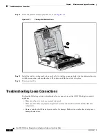
Страница 74: ...nector below the fan indicator lines up with the connection on the motherboard Push down until the fan clicks into place Step 16 Power on the ASA Troubleshooting Loose Connections Perform the following actions to troubleshoot loose connections on the ASA 5580 adaptive security appliance Make sure all power cords are securely connected Make sure all cables are properly aligned and securely connecte...

Страница 75: ...ing Loose Connections Make sure each device is properly seated If a device has latches make sure they are completely closed and locked Check any interlock or interconnect indicators that indicate a component is not connected properly If problems continue remove and reinstall each device checking the connectors and sockets for bent pins or other damage ...

Страница 76: ...4 26 Cisco ASA 5580 Series Adaptive Security Appliance Hardware Installation Guide OL 12920 01 Chapter 4 Maintenance and Upgrade Procedures Troubleshooting Loose Connections ...

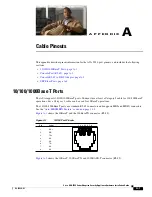
Страница 77: ... 1000BaseT Ports The ASA supports 10 100 1000BaseT ports You must use at least a Category 5 cable for 100 1000baseT operations but a Category 3 cable can be used for 10BaseT operations The 10 100 1000BaseT ports use standard RJ 45 connectors and supports MDI and MDI X connectors See the Auto MDI MDIX Feature section on page 1 13 Figure A 1 shows the 10BaseT and the 100BaseTX connector RJ 45 Figure...

Страница 78: ...bles Straight through Crossover Note Cisco does not provide these cables they are widely available from other sources Figure A 3 shows the RJ 45 cable Figure A 3 RJ 45 Cable To identify the RJ 45 cable type hold the two ends of the cable next to each other so that you can see the colored wires inside the ends as shown in Figure A 4 60915 2 3 1 4 5 6 7 8 Pin Label 1 2 3 4 5 6 7 8 TP0 TP0 TP1 TP2 TP...

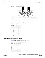
Страница 79: ...ence at both ends of the cable Crossover The first far left colored wire at one end of the cable is the third colored wire at the other end of the cable Table A 1 lists the rolled console cable pinouts for RJ 45 Console RJ 45 to DB 9 Adapter Table A 2 lists the cable pinouts for RJ 45 to DB 9 or DB 25 H5663 Table A 1 RJ 45 Rolled Console Cable Pinouts Signal Pin Pin Pin 1 8 2 7 3 6 4 5 5 4 6 3 7 2...

Страница 80: ...ules and connectors used in the ASA Table A 4 lists the SFP port cabling specifications for the SFP modules and connectors used in the ASA DSR 2 4 CTS 1 7 Table A 2 Cable Pinouts for RJ 45 to DB 9 or DB 25 continued Signal RJ 45 Pin DB 9 Pin Table A 3 Types of SFP Modules and Connectors Port Compliance Connector Fiber Type Gigabit Ethernet 1000BASE SX SW MMF 1000BASE LX LW SMF Table A 4 SFP Port C...

Страница 81: ... indicators 4 11 installing fans 4 11 interface cards 4 5 power supplies 4 6 installing in a rack 3 2 power supply indicators 1 7 removing interface cards 4 5 power supplies 4 6 specifications 1 13 T 15 Torx screwdriver 4 7 4 10 auto MDI MDIX 1 13 C chassis 1 9 loose connections 4 24 chassis covers removing 4 2 Cisco warranty 2 1 Console port 3 10 D Diagnostic Panel accessing 4 4 component list 1 ...

Страница 82: ...bed 1 11 illustration 1 11 I installing fans ASA 5580 4 11 interface cards ASA 5580 installing 4 5 removing 4 5 internal health information Diagnostic Panel 4 4 L loose connections chassis 4 24 M Management Port 3 9 MGMT port 3 10 P power supplies ASA 5580 installing 4 6 removing 4 6 power supply indicators ASA 5580 1 7 R Rack installation ASA 5580 3 2 RJ 45 connector pinouts A 3 S safety 2 1 site...

Страница 83: ...Index IN 3 Cisco ASA 5580 Adaptive Security Appliance Hardware Maintenance Guide OL 12920 01 V ventilation fans 2 4 W warranty 2 1 ...

Страница 84: ...Index IN 4 Cisco ASA 5580 Adaptive Security Appliance Hardware Maintenance Guide OL 12920 01 ...

Отзывы: