background image

- 73 - 


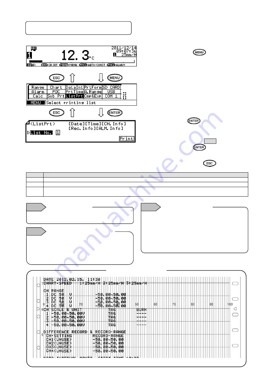
8-12.  List Printing Settings “ListPrt” 

List printing is used to check the set contents. Contents to be printed depend on the list number.


(1) Pressing 

the 

 key displays the 

menu window (list of setting items). 


(2) Select 

“ListPrt”. 


(3) Press 

the 

  key to make it available 

for setting and then select the list number. 
Contents to be printed will be shown on the 
right. 

(4)  Move the cursor to    Print .


(5) Pressing 

the 

  key moves cartridge 

pen to the end of the left side and the chart 
paper forwards slightly then starts list 
printing. Press the 

  key to cancel. 

Printed contents by List No.]


List No.


Printed contents


Date, Time, CH.Info (channel settings), Rec.Info (recording settings), ALM.Info (alarm settings)


Additional Setting, Option Setting Time


Date, Time, CH.Info (channel settings), Rec.Info (recording settings), 
ALM.Info (alarm settings), Additional Setting, Option Setting Time


To stop list printing, turn the recording status OFF and 
then ON again. List printing stops when the currently 
printing line is finished. When list printing is stopped, 
it cannot be resumed, so you need to set list printing 
again to perform it. 

Stopping list printing


Note 2

 
List printing is available only when recording is ON. 

Inexecutable case


Note 1


Example of list printing 

 
Trace printing by cartridge pen is not executed. Other 
operations are executed continuously without 
interruption. During list printing, setting change is not 
available. However, setting confirmation is available.

Operation at printing in process


Note 3


Содержание AH4000

Страница 1: ...INST No INE 879E AH4000 PEN TYPE Hybrid Memory Recorder General ...

Страница 2: ...on POC 67 8 9 Subtract Printing Settings Sub Prt 69 8 10 Periodic Data Interval Data Printing Settings DataInt 71 8 11 Periodic Specified Time Data Printing Settings PrtTime 72 8 12 List Printing Settings ListPrt 73 8 13 Message Printing 1 Settings MsgPrt1 74 8 14 Message Printing 2 Settings MsgPrt2 75 8 15 Recording Format Settings PrtForm 76 8 16 Auto Range Settings A Range 77 8 17 Compressed Ex...

Страница 3: ...ormal Measured Value 110 12 Inspection and Maintenance 111 12 1 Routine Inspection 111 12 2 Consumable Parts and Replacement Guideline 111 12 3 Battery removal method for the purpose of disposa 112 13 Option 114 13 1 External Operation Settings Dig Inp 114 13 2 Operation Recording Settings Ope Rec 117 13 3 COM Port Settings COM1 and COM2 118 13 4 IP Address etc Settings Ether 119 13 5 SNTP Setting...

Страница 4: ...nse even during warranty period 1 Failure or damage caused by improper use or connection or invalid repair or modification 2 Failure or damage caused by fire earthquake wind or flood thunderbolt or other extraordinary natural phenomena or pollution salt harmful gas abnormal voltage or use of unspecified power 3 Replacement of parts or accessories that have reached the end of their life Furthermore...

Страница 5: ...r panel mounting CG1 31039 Fixing screw 2 For panel mounting CG1 21062 Open end Wrench 1 CG1 31072 Terminal screw 5 M3 5 for input terminal spares for missing Chart paper 1 The type depends on the specifications Cartridge pen Analog pen 1 each Red 1st pen Green 2 nd pen Blue 3rd pen Brown 4 th pen Plotter pen Digital pen 1 Purple In addition if accessories are purchased additionally those products...

Страница 6: ... 0 to 1200 C 0 to 1400 C 0 to 1600 C 0 to 1800 C 400 to 1600 C 0 to 5mV 0 to 10mV 0 to 20mV 0 to 50mV 5 to 5mV 10 to 10mV 1 to 5V 4 to 20mA 10 to 50mA Double to sextuple scale Non standard scale EH05036 EH05035 EH05031 EH05034 EH05030 EH05048 EH01001 0 to 100 equal divisions The chart paper has the same printed linear scale as the standard scale Therefore it can be shared in regardless of input ty...

Страница 7: ...s cautions and basic operation 2 2 Symbol Mark This instruction manual includes the following symbol marks Make sure to fully understand the meaning of them Symbol mark Meaning Cautions are explained to avoid causes for death or serious injuries of users Cautions are explained to avoid causes for slight injuries of users or damages of the unit or peripheral devices 2 3 Label For safe use of the un...

Страница 8: ...use use the unit following the instruction manual Please note that CHINO does not have any responsibilities for any claims for failures or damages occurred with abuse or misuse of this recorder 6 Installing the safety device Regarding the use of devices that anticipates a big loss due to failure of this unit always install a safety device for preventing these losses and implement fail safe design ...

Страница 9: ...485 RS485 Alarm output remote contacts 0 None 2 2 mechanical relay a contact alarm outputs 4 4 mechanical relay c contact alarm outputs 5 remote contacts A 6 mechanical relay a contact alarm outputs 5 remote contacts 8 8 mechanical relay c contact alarm outputs 10 remote contacts B 12 mechanical relay a contact alarm outputs 10 remote contacts Power A 100 to 240V AC For OP SP NNN None ...

Страница 10: ...ivalent strength Select thickness of a panel considering weight and depth of the unit with panel formation for actual use 3 When mounting the recorder on the panel mount it according to the instruction manual for preventing injury 1 Panel cutout and mounting method Unit mm 281 1 0 1 0 281 360 360 Minimum interval on multiple units mounting Caution 241 When alarm output remote contacts unit and com...

Страница 11: ... Select a location distant from sources of electric field or magnetic field and without mechanical vibration or shock Overvoltage category II Altitude 2000m or less Pollution degree 2 Working place Indoor Short term temporary overvoltage 1440V Long term temporary overvoltage 490V Normal operating condition Ambient temperature 0 to 50 20 to 65 RH non condensing Ambient humidity 20 to 80 RH non cond...

Страница 12: ... 9 4 3 Wiring 1 Terminal board diagram The figure below is the diagram of the terminal board with the option Alarm relay output 12 points a contact remote contacts 10 points and communication interface ...

Страница 13: ... 10 The figure below is the diagram of the terminal board with the option Alarm relay output 8 points c contact remote contacts 10 points and communication interface ...

Страница 14: ... 11 The figure below is the diagram of the terminal board with the option Alarm relay output 2 points a contact and communication interface ...

Страница 15: ... unit and communication unit are removable 1 Every unit can be removed when two mounting screws are removed 2 The recorder and each unit are connected with a connector Turn off the power and then remove attach Make sure to turn off the external power switch before units are removed attached to prevent damages on electric circuits Input terminal block and alarm terminal block are removable Referenc...

Страница 16: ...c shock 2 Separate from strong power circuits For input output wiring avoid adjacency or parallel with strong power circuits such as power lines Separate 50cm or more for adjacency or parallel 3 Separate thermocouple input from heat sources To reduce reference junction compensation errors for thermocouple input especially separate terminals from heat sources heating body Also avoid radiation such ...

Страница 17: ...rminals other than the above M3 5 0 8Nm O type Y type Be sure to use O type for the alarm output terminals For other terminals use also O type as possible 6 Unused terminals Avoid using unused terminals for relaying Electric circuits may be damaged Treat the wired cables properly Treat the wired cable surely so that would not get tangle up on people and objects Disconnection of wiring may cause an...

Страница 18: ...ls have power supply voltage applied Make sure to install power terminal covers after wiring to prevent an electric shock Pay attention to power supply voltage and noise The power supply voltage of the unit is indicated on power terminals Applying power other than the indicated one causes accidents or malfunction In addition if the power has noise interference implement countermeasures such as noi...

Страница 19: ...rmometer cannot be connected in parallel with other instruments a controller or others mark on measurement input terminals High voltage may be applied to the measurement input terminals due to common mode noise Allowable noise value is 30VAC or 60VDC or less Check that the voltage is equal to or less than the allowable value Do not use the instrument for measurements on mains circuits Install term...

Страница 20: ... output terminals The terminal configuration depends on the output specification Alarm relay output 6 points a contact Alarm relay output 4 points c contact Alarm relay output 2 points a contact N O terminal M3 5 COM terminal M3 5 Alarm relay output 6 points COM terminal M3 5 N O terminal M3 5 COM terminal M3 5 N O terminal M3 5 ALARM RELAY 2 N O terminal M3 5 COM terminal M3 5 Alarm terminal 4poi...

Страница 21: ...e insulation or reinforced insulation to the outside circuit connected to an alarm output terminal should be set and industrial environment should be overvoltage category Ⅰ A buffer relay power supply is applied to the alarm output terminals after connections and so creates a risk of electric shock if touched Terminal cover must be mounted after connection Moreover safety measures to the outside c...

Страница 22: ... mechanical relay a contact output example and prevents wrong operation with light load Selection of buffer relay Coil rating Contact capacity or less of output terminals Contact rating Double of load current or more In addition the coil surge absorption element built in type relay is recommended If there is no buffer relay which meets the load rating implement another stage of buffer relay Select...

Страница 23: ...arning Upper row Remote contacts terminals Remote contact enabled operation name 1 Recording ON OFF and three chart speed selection two terminals of EX1 and EX2 are used 2 Messages No 01 and 02 selection and printing execution two terminals of EX1 and EX2 are used 3 Messages No 01 to 05 selection and execution four terminals of EX1 to EX4 are used 4 Digital data printing arbitrary one terminal 5 L...

Страница 24: ... printing with key is available 4 Operation which can be allocated to arbitrary terminal No ON Short circuit OFF Open Operation name Terminal contact signal 4 Digital data printing Turn ON the terminal No specified to Digital data printing Chart recording must be ON Digital data printing with key is enabled Even during execution the acceptance can be repeated only once 5 List printing List No 1 2 ...

Страница 25: ...of COM1 are to be specified on purchase 2 Communications cables Please prepare communication cables before wiring in advance Since exclusive cables are available from us place an order 1 RS232C Connection between PC and the unit or a line converter Cable 9 pin connector Crimp type ring terminals RS232C cable Shape Internal wiring Model code RZ CRS6 Cable length 01 to 15m specified Ethernet connect...

Страница 26: ...ween the unit and other devices Cable Crimp type ring terminals Crimp type ring terminals RS422A cable for parallel Shape 4 core cable of twisted 2 core cables of twisted VCTF lines Each side has a SG signal ground line Internal wiring Model code RZ CRA1 Cable length 01 to 99m specified Line converter side Recorder side RDB RDA SDA SDB SG SDB SDA RDA RDB SG Device side Recorder side SDB SDA RDA RD...

Страница 27: ...ct one to one connection use crossover twist pair cables with shield available locally as STP cable Connection between HUB and devices multiple devices can be connected For one to N connection between PC and devices via HUB use straight twist pair cables with shield available locally as STP cable 3 Communications line wiring 1 RS232C wiring PC and devices are connected one to one with RS232C Examp...

Страница 28: ...ge of the transmission line device side General metal film resistors will be fine They are available from us place an order Example of terminal connection Turn the switch of RS422A RS485 to RS422A Avoid connecting SG line to FG terminal or ground terminal of the device RDB RDA SDA SDB SG Termination resistor 100Ω Device side Line converter SC8 10 RDB RDA SDA SDB SD RD SG 1 2 3 4 5 6 7 8 Cable for ...

Страница 29: ... connection of devices one to one connection Crossover twist pair cable with shield Max 100m Device side PC side Device side HUB Straight twist pair cable with shield Max 100m PC side HUB Straight twist pair cable with shield Max 100m Straight twist pair cable with shield Max 100m Crossover twist pair cable with shield Max 100m Make sure to use crossover cable for connection of devices ...

Страница 30: ...e unit door The power switch is located at the upper left of the unit Display SD card slot Operation set keys Engineering port USB communication connector The front of the door is made of glass Avoid giving any shock to the glass or giving any strong force to the frame for preventing any injury due to breakage How to handle the door Note ...

Страница 31: ...eed of 600mm min while this key is pressed DATAP Data print Prints the data at the time of pressing this key Used with the key FUNC1 Function 1 key Switches and sets functions function is shown on the display FUNC2 Function 2 key Switches and sets functions function is shown on the display MENU Menu key Displays various setting items ESC Escape key Returns to the previously displayed screen Up Dow...

Страница 32: ...d then close the chart guide and chart feeding holder opened in the step 1 5 Turn the thumb wheel downward and make sure that the holes on the both ends of chart are not released from the sprockets and feeding is smoothly done 3 Returning the chart cassette to the inside of the unit 1 Align the guide of the chart cassette with the guide rail located at the both sides of the internal chassis and th...

Страница 33: ...dge pen and plotter pen stop at standby position and rise up 3 Prepare each pen After opening aluminum package remove the pen cap 4 Open the door and display panel to the same direction 5 Replace the pens while the chart cassette is in the housing 3 Pen replacement mode Rep Pen 1 Set to the pen replacement mode Pressing key displays menu screen programming items 2 Select Rep Pen 3 Press key and st...

Страница 34: ...mpossible 2 Pen cap Each pen is provided with a pen cap for preventing drying and protecting the pen tip Remove and retain the pen caps before setting the pen For stopping the recording more than a day remove the pen then put the cap on and store it Maintenance of pens Insert the plotter pen until it makes clicking sound When the insertion is done correctly A part fits into the penholder Incorrect...

Страница 35: ...etting and then set the display language with the keys Language can be selected from English and Japanese When setting is completed move the cursor to Set and press the key to register the setting The language setting can also be set later Refer to 8 28 Soft Dip Switch Settings in the instruction manual for General provided separately Backup of settings clock and display mode are made However chan...

Страница 36: ... Chart end recording ON Data print list print Date time Chart speed AUTO CONST Key lock POC Recoding point indicator SD card remaining amount Key guide CHNo Measured value Chart end recording ON Data print list print Key lock POC SD card remaining amount CHNo Measured value TAG or Unit Chart end recording ON Data print list print Time Chart speed Key lock POC Recoding point indicator SD card remai...

Страница 37: ...the printing is turned off each pen lifts up automatically Even if the power is turned off in this condition this pen position is maintained 2 When the chart cassette is pulled out each pen lifts up If the printing has been turned off when pulling out the chart cassette each pen has already been lifted up and it maintains its position Up and down of pens Reference 1 The table below explains the pr...

Страница 38: ...re trace printing is interrupted and data printing is started Press the key key to perform data printing Use the periodic data printing function to perform data printing periodically This cannot be performed while recording is OFF or keys are locked Operation Operations including measurement continue without being interrupted Cancel To stop data printing halfway through press the key key Then pres...

Страница 39: ... mark as viewed from the front by pressing the key do not align it manually 3 It may be a good idea to set a time scale line 1 to 2mm above the setting mark to perform a fine adjustment later 4 Press the key and turn off the REC status LED 5 Press the key at a desired time xxh 00min and turn on the REC status LED 6 After a few hours check to see if the time line print is aligned with a time scale ...

Страница 40: ...cified parameters when required Fixed time printing Prints date year month date time time line linked to the chart speed and printed chart speed max min chart record channel number and tag and unit Message printing Prints a message which can contain up to 72 characters Calendar timer printing Prints when both calendar timer is ON OFF and printing are set to ON Operation recording When using remote...

Страница 41: ...ng 30min Example 1 Time line 2 Time 3 POC mark print only when time axis synchronization is ON 2 Printing interval of max min chart record channels number and tag and unit 1 These are printed at intervals of 42mm and in order of channel number 2 Tag is not printed if not specified 3 When you set the recording format printing contents vary depending on the selected format 4 Printing mode is differe...

Страница 42: ... printing range described in 8 2 Input Type Settings No Input status Display Printing Digital Digital Trace 1 Input under the lower limit of measuring range OVER OVER Downscale burnout 2 Input under the lower limit of chart printing range Normal display Normal print 3 Input over the upper limit of chart printing range Normal display Normal print Upscale burnout 4 Input over the upper limit of meas...

Страница 43: ...e 50 00 to 50 00 3 Scale 50 00 to 50 00 4 Unit V 5 Tag Not set 6 Display printing On and OFF 1 Display 2 Trace printing 3 Digital printing 4 SD card recording All channels ON All channels ON All channels ON All channels ON 7 Chart speed 25mm H 8 Digital recording printing Data interval None 9 Alarm settings Not set 10 Subtract printing settings Not set 11 Message settings Not set 12 Password 3571 ...

Страница 44: ... displayed at the left of each parameter Move the cursor to a desired parameter using the keys 4 Key acceptance and acceptance failure When the cursor does not move by pressing the keys or when a parameter setting window does not open by pressing the key it indicates that the keys have been unaccepted Make sure to press the keys properly and try again 5 Number of setting items and parameters Setti...

Страница 45: ...selection areas Use the keys to select an insert or change position while is displayed at the left of the parameter entry area When you enter a character string exceeding the valid number of digits the last digit will be deleted Note Pressing the key switches the entry mode alphabets numbers symbols and katakana The mode to be switched depends on the parameter When the key is pressed after setting...

Страница 46: ...cify 0 position of chart with REC L and 100 position with REC H 5 Sensor correction Measurement value is offset by the specified value Use this function to adjust the zero point 6 Unit Arbitrary characters can be set as unit However when numeric characters are set you may find it difficult to distinguish the unit from measured data at data printing Up to six digits can be set and upper two digits ...

Страница 47: ... also installed to smooth slight variations of the measuring input The value for the programming is corresponding to Time constant T 10 Recording deadband The input filter has a function to stabilize the measuring input The pen does not move until the variation of the measurement input exceeds the set amount Setting value 0 05 mm per 1 When 0 the function is invalid T A 0 63 Input filter None Inpu...

Страница 48: ... a value 6 After completing the settings of this item move the cursor to Set 7 Press the key to register the settings when chart recording is ON a setting change mark is printed To cancel the settings press the key Note Actual windows are separated Use the keys to scroll and continue settings CH No is fixed to the one selected from the list of set contents The input type RJ burnout and ON OFF of e...

Страница 49: ...e constant of input filter sec None None 0 5s 1s 2s 3s 4s 5s UNIT Set a character string of up to six characters V TAG Set a character string of up to 10 characters Not set Disp Select ON or OFF for measured value display ON ON OFF Rec Select On or OFF for trace printing ON ON OFF DIGI REC Select On or OFF for digital recording printing ON ON OFF SD CARD REC Select On or OFF for SD card recording ...

Страница 50: ...Activated 1 Time 2 CH 3 Alarm type 4 Level 2 Alarm setting parameters The alarm function does not work initially since it is not set prior to shipment 1 Alarm point alarm type and alarm value Alarm type upper lower diff upper lower or rate of change upper lower and alarm point can be set for up to four levels per channel at arbitrary points 2 Alarm deadband Alarm is activated when a measured value...

Страница 51: ...set the measured value stops flashing and ALM is turned off they keep flashing when alarm display and relay output is held You can stop flashing of measured value and status LED from the alarm status check window if the alarm has been reset When remote contact is selected as a reset method specify the remote contact No which executes a reset Hold EX Not Hold Hold Reset by KEY Hold Reset by EX Sele...

Страница 52: ...when the difference calculated by subtracting the measured value of compared channel from the measured value of specified channel reaches or falls below an alarm value Set value alarm value compared CH deadband Activation condition specified CH data compared CH data alarm value Reset condition specified CH data compared CH data alarm value deadband 5 Rate of change upper limit alarm U Alarm is act...

Страница 53: ... width PV2 PV1 D U Upper alarm Lower alarm Alarm value of D Alarm value of U Rate of change alarm Difference in measured value absolute value alarm value diff upper alarm activated Difference in measured value absolute value alarm value diff lower alarm activated Diff upper alarm Alarm activated Alarm value Difference Absolute value Alarm activated Alarm value Difference Absolute value Diff lower ...

Страница 54: ...then select or enter a value 6 After completing the settings of this item move the cursor to Set 7 Press the key to register the settings when chart recording is ON a setting change mark is printed To cancel the settings press the key Note Actual windows are separated Use the keys to scroll and continue settings The decimal point position of alarm value deadband is linked to that of scale set valu...

Страница 55: ... 1 to 20 Hold DISP Select whether to hold the status of display and ALM status LED at alarm activation Not Hold Hold Reset by KEY hold until reset by key operation Hold Reset by EX hold until reset by remote contact Hold OUT Select whether to hold the status of alarm output at alarm activation Not Hold Hold Reset by KEY hold until reset by key operation Hold Reset by EX hold until reset by remote ...

Страница 56: ...d is shown on the window When alarm condition is cleared on the channel selecting Hold for alarm output and display and KEY as a reset method Hold Reset by KEY select the channel with the keys and press the key to reset the Hold status This alarm status check window contains the information obtained at the time the key is pressed on the measured value display window To view the latest information ...

Страница 57: ...ale upper limit Sz scale lower limit Decimal point position for result Channel No of data Rx Humidity Calculated from measured value of dry bulb x and wet bulb y using relative humidity table x y channel data Decimal point position for result Channel No of data x y Max value High Peak Maximum measured value x in an interval Decimal point position for result Interval Start time Channel No of measur...

Страница 58: ...Unit Time 2 T T PV PV INT INT 1 n n 1 n n 1 n n INTn Integration value INTn 1 Last integration value PVn Current measured value 1 PVn 1 Last measured value 1 Tn Current measurement time sec Tn 1 Last measurement time sec Time Unit Unit of time 1 When the scale width is exceeded the value at the maximum minimum scale is used 1 Resetting integration 1 Reset by remote contact When using remote contac...

Страница 59: ...w Also pressing the key displays the copy window for calculation settings 4 Move the cursor to the parameter to be set with the keys 5 Press the key to make it available for setting and then select or enter a value 6 After completing the settings of this item move the cursor to Set 7 Press the key to register the settings when chart recording is ON a setting change mark is printed To cancel the se...

Страница 60: ... when arithmetic 1 or 2 is selected for Kind 30000 to 99999 Up to three digits after decimal point can be set Example 30 000 Const C Set calculation constant C when arithmetic 1 is selected for Kind 30000 to 99999 Up to three digits after decimal point can be set Example 30 000 Const D Set calculation constant D when arithmetic 1 is selected for Kind 30000 to 99999 Up to three digits after decimal...

Страница 61: ...than or equal to X Y Less than or equal to X Y X and Y represent formula or numeric value Logical operation Logical operation is performed and either 1 or 0 is returned as a result Symbol Example Note Logical AND AND X AND Y Parenthesize formula target Logical OR OR X OR Y Parenthesize formula target Exclusive OR XOR X XOR Y Parenthesize formula target Negation NOT NOT X Parenthesize negation targ...

Страница 62: ...t per unit time X represents channel number When a formula specifies a calculation result in it and the specified channel No is larger than the calculating channel No the last calculation result will be used Function to get system information Symbol Example Note SD card remaining amount SD SD A A unit of remaining amount 0 Other functions Symbol Example Note Wind display AZI AZI A See 10 Wind disp...

Страница 63: ...ormal integration 3 F value Entering a formula FV X To Z R X Channel No of calculation target To Reference temperature for F value calculation Z Z value R Start temperature for F value calculation F value is obtained from the following calculation 10A dt where A T To Z T Calculation target channel data When T value exceeds R value F value will be reset to 0 4 Relative humidity Entering a formula R...

Страница 64: ...7 K x 9 677843E 3 K x 0 62215701E 6 K x 0 20747825E 8 9 484024E 13 x K 4 1635019 x LOG K 1000 3 S W x h 100 4 P S x 1000 5 Y LOG P 6 When P 611 2 D 77 199 Y x 13 198 Y x 0 63772 0 071098 x Y When P 611 2 D 60 662 Y x 7 4624 Y x 0 20594 0 016321 x Y 6 Moving average Entering a formula AVE X T X Data channel No T Time line range x 0 1sec An average value in the past T seconds is calculated AVE Sampl...

Страница 65: ...a reset of integration value occurs at a set time or by another reason except overflow because the same process as overflow reset is performed internally Formulate the operation in consideration of reset of integration value 10 Wind display Entering a formula AZI A A Wind data Wind display is made by converting numeric data into direction See the following table for the relation between wind data ...

Страница 66: ...rs An X1 An 1 Bn 1 Bn An 1 An x X1 An Bn 12 Examples of combining different operations CH 1 3 20 6 Channel 1 raw data x 3 20 6 CH 1 CH 2 300 Result will be 1 when the sum of channel 1 and channel 2 raw data is smaller than 300 ABS CH 1 50 Result will be 1 when the absolute value of channel 1 is greater than or equal to 50 PCH 1 100 AND PCH 2 50 Result will be 1 when the channel 1 data is greater t...

Страница 67: ...plays the copy window for formula settings 4 Press the key to make it available for setting and then enter a formula 5 After completing the setting of this item move the cursor to Set 6 Press the key to register the setting when chart recording is ON a setting change mark is printed To cancel the setting press the key Formula setting parameter Parameter Function Default Set value Formula Set formu...

Страница 68: ...r to be set with the keys 5 Press the key to make it available for setting and then enter a value 6 After completing the settings of this item move the cursor to Set 7 Press the key to register the settings when chart recording is ON a setting change mark is printed To cancel the settings press the key List of Seg Tbl setting parameters Parameter Function Default Set value X Dot Set decimal point ...

Страница 69: ...ng is ON a setting change mark is printed To cancel the settings press the key List of Chart setting parameters Parameter Function Default Set value ChartSpeed1 Set chart speed 1 25 1 to 600 mm H 1 to 200 mm M ChartSpeed1unit Select unit of chart speed 1 Mm H mm H mm M ChartSpeed2 optional Set chart speed 2 25 1 to 600 mm H 1 to 200 mm M ChartSpeed2 unit Select unit of chart speed 2 mm H mm H mm M...

Страница 70: ...ta Printing OFF When the printing is ON 2nd pen stores data of gaps G1 to 1 st pen in memory and start printing on same time axis as 1st pen When the printing is OFF the data of gaps G2 to 1st pen are deleted G2 G1 Time axis synchronization executed Pen gaps Plotter pen 1 st pen 4 5mm 1 st pen 2 nd pen 4 0mm 2 nd pen 3 rd pen 4 0mm 3 rd pen 4 th pen 4 0mm Installation position for AH4000 1 Time ax...

Страница 71: ...ey to register the settings when chart recording is ON a setting change mark is printed To cancel the settings press the key List of POC setting parameters Parameter Function Default Set value POC ON OFF Select time axis synchronization ON OFF OFF OFF without synchronization ON with synchronization Print marks listed below when switching ON or OFF 1 Time of change 2 POC mark 3 ON or OFF 1 2 3 Time...

Страница 72: ...ing range for subtract printing is required and it is set by specifying the upper and lower limits Also unit is set when needed It is necessary to estimate difference value beforehand to set the chart recording range Note 3 Subtract printing 1 Channel C data 2 Channel E data Channel A data Channel B data Channel D data Reference value Set Const reference value within five digits The decimal point ...

Страница 73: ...ettings when chart recording is ON a setting change mark is printed To cancel the settings press the key List of Sub Prt setting parameters Parameter Function Default Set value Kind None None CH X CH Y CH X Const CH X Set measuring CH as minuend 1 to 4 CH Y Set measuring CH as subtrahend 1 to 4 Const Set reference value subtracted from CH X 30000 to 99999 Decimal point position is the same as CH X...

Страница 74: ...ng parameters Parameter Function Default Set value StartTime Set start time of periodic data printing When a set time is before the current time periodic data printing is executed next day 00 00 00 00 to 23 59 Interval Set interval between printings of numeric measured data every 24 hours 59 minutes and 1 minute at maximum 00 00 00 00 to 24 59 The shortest interval depends on the chart speed and t...

Страница 75: ...printing at specified time Also pressing the key displays the copy window for specified time data printing settings 4 Move the cursor to the parameter to be set with the keys 5 Press the key to make it available for setting and then enter a value 6 After completing the setting of this item move the cursor to Set 7 Press the key to register the setting when chart recording is ON a setting change ma...

Страница 76: ...o recording settings ALM Info alarm settings 2 Additional Setting Option Setting Time 3 Date Time CH Info channel settings Rec Info recording settings ALM Info alarm settings Additional Setting Option Setting Time To stop list printing turn the recording status OFF and then ON again List printing stops when the currently printing line is finished When list printing is stopped it cannot be resumed ...

Страница 77: ...rs other than No Also pressing the key on this window prints the message of selected No When Start printing is displayed press the key Pressing the key displays the copy window for message settings 4 Move the cursor to the parameter to be set with the keys 5 Press the key to make it available for setting and then select or enter a value 6 After completing the settings of this item move the cursor ...

Страница 78: ...lect or enter a value 5 After completing the settings of this item move the cursor to Print 6 Pressing the key displays the message Start printing Press the key again to start message printing Press the key to cancel printing List of MsgPrt2 setting parameters Parameter Function Default Set value Message Set a string consisting of up to 72 characters to be printed Not set 5mm Feed No Prints messag...

Страница 79: ...e is shifted automatically depending on the input range Compressed expanded printing Chart recording area can be partially shrunk or expanded Zone printing Chart recording area can be divided into four areas at maximum 1 Pressing the key displays the menu window list of setting items 2 Select PrtForm 3 Press the key to make it available for setting and then select a value 4 After completing the se...

Страница 80: ...e a copy function for the setting However note that the decimal point position depends on the value at destination even if the source value has different decimal point position Example Source value 120 3 value at destination 20 05 value after copy 12 03 indicates a set point The order of setting is shown by numbers 1 to 5 In this example the range 5 is not used For an unused range move the cursor ...

Страница 81: ...gs press the key List of A Range setting parameters Upper section Auto Range Normal Lower section Auto Range Overlap Parameter Function Default Set value Auto Range ON OFF OFF ON enabled OFF disabled 1st Min Set lowest end of 1st range None 30000 to 99999 Decimal point position is the same as CH scale setting 1st Min Set lowest end of 1st range 1st Max Set highest end of 1st range None 30000 to 99...

Страница 82: ...et arbitrarily regardless of the setting of range chart recording upper and lower limits Up to two break points can be set therefore three shrunk or expanded areas can be obtained at maximum indicates a set point Example of compressed expanded printing settings Entire recording range Scale 1st break point 2nd break point Compressed Expanded Compressed Recording position 200 1370 100 600 800 1200 0...

Страница 83: ...ing the settings of this item move the cursor to Set 7 Press the key to register the settings when chart recording is ON a setting change mark is printed To cancel the settings press the key List of Cmp Exp setting parameters Parameter Function Default Set value SCALE 0 Set recording scale at 0 recording position None 30000 to 99999 Decimal point position is the same as specified CH scale POS 1st ...

Страница 84: ... specified by range chart recording upper and lower limits See the following table for recording positions mm which vary by the number of divisions Division 1st area 2nd area 3rd area 4th area 2 0 to 81 99 to 180 3 0 to 54 63 to 117 126 to 180 4 0 to 36 45 to 81 99 to 135 144 to 180 Recording position mm This example specifies CH1 and Ch3 for the 1st area and CH2 and CH4 for the 2nd area See Area ...

Страница 85: ...pe Area specification format Selected from options CH X CH X CH X CH Y CH X CH Y CH X CH Y CH Z CH X CH Y CH Z CH X CH Y CH Z CH X Not used 1 to 4 CH Y Not used 1 to 4 CH Z Not used 1 to 4 Note Actual windows are separated Use the keys to scroll and continue settings The number of areas increases as you select a greater number for division Zone resulting in the need of setting more parameters CH X...

Страница 86: ...d prevent loss or damage to your property Never disassemble or modify SD card It may result in fire electric shock or malfunction Do not use SD card in a location where it may get wet or condensation occurs The internal circuit of SD card may be damaged in such a location Do not handle attach remove SD card near small children to avoid accidental ingestion or other dangerous situations Do not stor...

Страница 87: ...ate the start trigger with keys set the start trigger to other than None Even when the start trigger is set to other than Key a start by key operation is given higher priority than other methods The same can be applied to the end trigger Both start and end triggers can be executed on any window The confirmation message Start recording to SD Card or Quit recording to SD Card will be displayed by pr...

Страница 88: ...f samples is recorded to SD card when recording is started When the recording interval is less than 1 second the number of samples is fixed to 10 except for setting 0 00 0 to 10 Note Past data is initialized when settings are changed or card is inserted removed When PreTrigger is set the recording interval synchronizes with past data so there may be a case that measured data at recording start tim...

Страница 89: ...Also the file is divided if device setting or date and time setting is changed File division Note 5 A measured data file is saved in a folder created each year month within the HR_DATA folder for example a folder is named HR201101 for Jan 2011 Also a setting parameter file is saved in the HR_SET folder File save location Reference ...

Страница 90: ...c characters up to eight digits 5 After completing the settings of this item move the cursor to Set 6 Press the key When Start Saving is displayed press the key to start saving setting parameters to SD card To cancel saving press the key You cannot specify the same name for files even if they have different numbers Setting file name Note 1 The maximum number of setting parameter files which can be...

Страница 91: ...d 1 Select SD CARD from the menu window list of setting items 2 Move the cursor to Remove beside SD Card and press the key 3 When Stop the SD Card is displayed press the key Press the key to cancel 4 Make sure that the green CARD status LED in the operation set keys section turns off and then remove SD card When you load setting parameters all the current parameters will be overwritten Save the cu...

Страница 92: ...start formatting Selecting a file No and pressing the key can remove the selected file from SD card When Delete is displayed press the key to delete the file On the setting file list window files are displayed in the chronological order with a file having the oldest update date listed first File display order Reference To use SD card at its maximum performance format it periodically Periodic maint...

Страница 93: ...ach unit when connecting multiple units up to five units to a PC Set USB ID to 1 when using the provided programming software Only one unit can be connected to a PC 1 Pressing the key displays the menu window list of setting items 2 Select USB 3 Press the key to make it available for setting and then enter a value 4 After completing the settings of this item move the cursor to Set 5 Press the key ...

Страница 94: ...tting and then select or enter a value 6 After completing the settings of this item move the cursor to Set 7 Press the key to register the settings when chart recording is ON a setting change mark is printed To cancel the settings press the key List of Timer setting parameters Parameter Function Default Set value Mode Select timer type None None ON specify ON time only ON OFF specify both ON and O...

Страница 95: ...ysInfo from the menu window Each alarm is turned off when the alarm condition is cleared or alarm operation is disabled in this setting individual setting available 1 Pressing the key displays the menu window list of setting items 2 Select FailOut 3 Move the cursor to the parameter to be set with the keys 4 Press the key and check the check box of required items Also set the desired relay No for o...

Страница 96: ...D LCD display LED LED indication E mail Relay relay output Check a check box of desired item SD Card Relay No Set alarm output relay No at detection of SD card low capacity No output 99 internal circuit output 1 to 12 SD Card And Or Select circuit type of alarm output at detection of SD card low capacity Or And Or Battery Set alarm operation at detection of backup battery low level Not selected LC...

Страница 97: ... Select unit or tag to be displayed Unit Unit Tag Both tag and unit Only 04CH 03CH Bar display mode is valid For 1 pen type and 2 pen type display become and unable to set Auto Const Select either manual key or auto update interval for display CH update Auto Auto Const CH Update Interval Set update interval of display CH 2sec 1sec 2sec 3sec 5sec 10sec 30sec Data update interval Set data update int...

Страница 98: ...of update display from 01 to04 4 Press the key to make it available for setting and then enter CH No 5 After completing the setting of this item move the cursor to Set 6 Press the key to register the setting when chart recording is ON a setting change mark is printed To cancel the setting press the key D Order setting parameter Parameter Function Default Set value CH No Set CH No to be updated dis...

Страница 99: ...to the parameter to be set with the keys 4 Press the key to make it available for setting and then enter a value 5 After completing the settings of this item move the cursor to Set 6 Press the key to register the settings when chart recording is ON a setting change mark is printed To cancel the settings press the key List of Date setting parameters Parameter Default Set value Year Current time has...

Страница 100: ...on state Terminal configuration differs depending on the alarm output specification 1 Mechanical relay a contact output Relay mode Power OFF Alarm reset Alarm activation Norm Open Norm Close 2 Mechanical relay c contact output Relay mode Power OFF Alarm reset Alarm activation Norm Open Norm Close N O COM N C N O COM N C N O COM N C N O COM N C N O COM N C N O COM N C N O COM N O COM N O COM N O CO...

Страница 101: ... change mark is printed To cancel the settings press the key Press the key to display Start Initializing then press key to execute memory clear To cancel the settings press the key System setting parameters Parameter Function Default Set value Key Lock Set disabling settings change by key Not set Select at checkbox Initialize Set memory clear Not set Select at checkbox Rec Adj Adjust of Rec positi...

Страница 102: ... displays the system information Item Contents TYPE Model code of the unit excluded No Serial number of the unit MAC Adr MAC address of the unit using Ethernet option This field is left blank when Ethernet option is not used SP Additional information 0X00000000 displayed normally System Value Value depends on the unit specification P Printer software version A E Application software version I Prea...

Страница 103: ...witch setting on setting software 1 Pressing the key displays the menu window list of setting items 2 Select SoftDip 3 Move the cursor to the parameter to be set with the keys 4 Pressing the key switches ON OFF 5 Pressing the key displays the confirmation screen Press the key to register the settings The confirmation screen is displayed regardless of setting change 6 Turn off the power after the s...

Страница 104: ...Time Print Yes Print fixed time except time line and time printing OFF No print ON Print ON U08 OFF Time Print No ON Time Print Yes Print time line and time printing of fixed time printing OFF No print ON Print ON U09 OFF DataInterval Format Normal ON DataInterval Format Special Switch time format of periodic data printing OFF Hour minute ON Year month day hour minute OFF U10 OFF Feed After Date N...

Страница 105: ...or cartridge pen and plotter pen position on a chart This adjustment does not affect the measured value Before performing this adjustment enable Adjust of Rec position according to 8 26 System Settings When it is enabled Rec Adj is shown on the menu window list of setting items 1 Pressing the key displays the menu window list of setting items 2 Select Rec Adj 3 Set pen No with the keys Each time p...

Страница 106: ...adjustment is completed press the key to register the span position 8 While the adjustment window is displayed you can perform adjustment by pressing the key or key as many times as you need When the adjustment is completed press the key to exit the trace printing position adjustment Zero and span can be adjusted separately To adjust the 0 position only press the key when the adjustment is complet...

Страница 107: ...ng the adjustments 4 At first reference pen record a straight line on the chart paper Pressing the key feeds the chart and moves cartridge pen little to the right A cross point of a straight line recorded by a reference pen and a trajectory of the cartridge pen is adjustment ending point Pressing 5 After completing the adjustment of this item press key to register the recording position 6 Press ke...

Страница 108: ...er limit and range upper limit set in 8 2 Input Type Settings Zero input 5 Apply the range lower limit specified in the Zero field by the tester 6 Press the key to take the input Span input 7 Apply the range upper limit specified in the Span field by the tester 8 Press the key to take the input 9 When zero and span inputs are completed correction values will be displayed automatically at A and B I...

Страница 109: ...t value with Inp Adj described in the previous section See 9 3 Input Adjustment 1 Display the input adjustment window shown on the left and enter 1 to the A parameter entry field and a shift value to the B parameter entry field If an input adjustment has already been performed and values have been specified in the A and B fields add a shift value to the B parameter 2 After completing the setting m...

Страница 110: ...n using the shift adjustment function to adjust measured value the shifted value should be taken into account When you change the wiring with the terminal cover removed energize the unit for at least 30 minutes after attaching the terminal cover and then perform adjustment The accuracy of the unit is 0 1 Therefore you need to use a tester having higher degree of accuracy to perform proper adjustme...

Страница 111: ...t this engineering port is designed for temporary communication connection and not intended for always on connection To obtain always on connection for communication you need to request the model with communication interface at the time of purchase and use the terminal located at the rear side of the unit for permanent connection Make sure to attach or remove an engineering cable to from the engin...

Страница 112: ...manually and make sure that the chart can be fed smoothly 2 Make sure that the chart can be fed smoothly with the key See 6 2 4 Chart recording operation 5 keys not accepted Check the system settings See 8 26 System Settings While Key Lock is active is shown on the display 6 Range setting done but data display or trace digital printing not performed on a certain channel 1 Check the setting ON OFF ...

Страница 113: ...ut of the measuring range 3 Error occurs in measured value 1 Check if error occurs in the input signal 2 Make sure that a compensation lead wire is connected to the input terminal thermocouple input only 3 Check the scale and perform input adjustment if error occurs 4 Measured value influenced by ambient temperature thermocouple input only 1 Check if RJ is set to EXT external in input type setting...

Страница 114: ...mechanical section such as the main shaft and gear 12 2 Consumable Parts and Replacement Guideline The unit includes some consumable parts To use the unit for a long time in good condition we recommend that these parts be replaced regularly Do not replace parts other than chart and pens by yourself Not only does it fail to replace properly but it also may pose dangerous situation Make sure to cont...

Страница 115: ...en the unit door and then open the display board in the same direction 2 Turn OFF the power switch 3 Remove two screws fixing the internal chassis 4 Remove one screw fixing the mechanical side panel and then pull out the internal chassis 5 Remove chassis back side cable 6 Remove two Chassis front unit fixing screw and pull out chassis front unit Caution Mechanical side panel fixing screw Chassis f...

Страница 116: ...emical substance no more than the defined amount by RoHS 2 The unit must be disposed of by a waste disposal company or in accordance with the local regulations 3 The unit uses a lithium battery and the battery must be disposed of by a waste disposal company 4 The packing materials used for the unit such as box plastic bag cushion and sticker should be sorted for recycling in accordance with local ...

Страница 117: ...cific terminal numbers ON short OFF open Operation name Terminal contact signal 1 Select chart speed from three speeds Three chart speeds should be set as well as the setting described in this section See 8 7 Chart Speed Settings Recording ON OFF and chart speed selection Between COM and EX terminal EX1 EX2 Recording ON CS1 OFF OFF CS2 ON OFF CS3 OFF ON Recording OFF ON ON Chart recording should b...

Страница 118: ...ion reset See 8 4 Calculation Settings 7 Message printing No 01 to No 20 Message should be set as well as the setting described in this section See 8 13 Message Printing 1 Settings Turn ON the terminal No specified for message printing No 01 to 20 Chart recording should be ON Message printing can be executed also by keys 8 Time correction When the current time second is 0 to 30 the second value wi...

Страница 119: ...the key to register the setting when chart recording is ON a setting change mark is printed To cancel the setting press the key Dig Inp setting parameter Parameter Function Default Set value Mode Allocate function to specified remote contact terminal No None None not used ChartSpeed chart speed Message 1 2 message 1 2 printing Message 1to5 message 1 to 5 printing DataPrint ListPrint 1 list 1 print...

Страница 120: ...EX Also pressing the key on this window displays the copy window for operation recording settings 4 Move the cursor to the parameter to be set with the keys 5 Press the key to make it available for setting and then select or enter a value 6 After completing the settings of this item move the cursor to Set 7 Press the key to register the settings when chart recording is ON a setting change mark is ...

Страница 121: ...meters Parameter Function Default Set value Mode Communication mode Low To PC etc Fixed to Low To PC etc Protocol Select communication protocol MODBUS RTU MODBUS RTU MODBUS ASCII PRIVATE1 without connection sequence PRIVATE2 with connection sequence Address Set communication address of the unit 01 01 to 99 Baud rate Set communication speed 9600 PRIVATE 1200 2400 4800 9600bps MODBUS 9600 19200 3840...

Страница 122: ...value Setting disabled IP Address Set IP address 192 168 254 254 each area is set to 0 to 255 Subnet Mask Set subnet mask 255 255 255 0 each area is set to 0 to 255 Default Gateway Set default gateway address of the network used 0 0 0 0 each area is set to 0 to 255 DNS ON OFF Select whether to use DNS domain name server OFF OFF not used ON used Set server like SNTP and SMTP by the name when using ...

Страница 123: ... 5 After completing the settings of this item move the cursor to Set 6 Press the key to register the settings when chart recording is ON a setting change mark is printed To cancel the settings press the key List of SNTP setting parameters Parameter Function Default Set value ON OFF Set whether or not to use time setting function by SNTP OFF OFF not used ON used Server Set SNTP server name or IP ad...

Страница 124: ...leting the settings of this item move the cursor to Set 7 Press the key to register the settings when chart recording is ON a setting change mark is printed To cancel the settings press the key Note Actual windows are separated Use the keys to scroll and continue settings List of E mail Account setting parameters Parameter Function Default Set value POP3 Server Set server name or IP address used f...

Страница 125: ...and press the key The cursor does not move to parameters other than No 5 Press the key to make it available for setting and then enter a destination address 6 After completing the setting of this item move the cursor to Set 7 Press the key to register the setting when chart recording is ON a setting change mark is printed To cancel the setting press the key E mail Address setting parameter Paramet...

Страница 126: ...the settings when chart recording is ON a setting change mark is printed To cancel the settings press the key List of E mail Condition setting parameters Parameter Function Default Set value Condition Select E mail transmission condition None None not used Alarm at alarm activation Interval send measured value at fixed intervals FailOut Target CH Set beginning and end of target CHs to send e mail ...

Страница 127: ...shrunk or expanded Automatic range shift Recording range is shifted automatically to another set range when measured value exceeds the current range Overlap function available Periodic data printing Digital printing is added to trace printing at 1 arbitrary intervals or 2 specified time Printed items Time CH No data and unit 1 Set interval and start time Interval is limited by chart speed 2 Set ti...

Страница 128: ...nals Exterior material Front Door Aluminum die casting ADC12 Glass Soda glass Rear Case Cold rolled steel plate SPCC Exterior color Front Door Black equivalent of Munsell N3 0 Glass Clear and colorless Rear Case Gray equivalent of Munsell N7 0 Dimensions 288H x 288W x 220D 241D with the alarm output remote contact unit or communication unit D indicates the panel depth Terminal screw Power terminal...

Страница 129: ... 1digit 0 to 400 C 0 2 FS 1digit 0 to 1760 C 27 6mV 1 C S 0 to 1300 C 13 8mV 1 C 0 1 FS 1digit 0 to 400 C 0 2 FS 1digit 0 to 1760 C 27 6mV 1 C B 0 to 1820 C 13 8mV 1 C 0 1 FS 1digit 0 to 400 C undefined 400 to 800 C 0 2 FS 1digit N 200 0 to 400 0 C 13 8mV 0 1 C 0 1 FS 1digit 200 to 0 C 0 2 FS 1digit or equivalent of 70µV whichever is larger 200 0 to 750 0 C 27 6mV 0 1 C 200 to 1300 C 69 0mV 1 C U ...

Страница 130: ... accuracy is added for thermocouple input Under EMC test condition variation in indication value may be 20 or 2mV at maximum whichever is larger K E J T R S B N IEC584 1977 and 1982 JIS C 1602 1995 JIS C 1605 1995 W WRe26 NiMo Ni Platinel II PtRh40 PtRh20 CR AuFe Au Pt ASTM E1751 WRe5 WRe26 ASTM E988 U L DIN43710 1985 Pt100 IEC751 1995 JIS C 1604 1997 Old Pt100 IEC751 1983 JIS C 1604 1989 JIS C 16...

Страница 131: ...CHINO CORPORATION 32 8 KUMANO CHO ITABASHI KU TOKYO 173 8632 Telephone 81 3 3956 2171 Facsimile 81 3 3956 0915 Printed in Japan ...

Отзывы: