


40
Additional control capabilities include automatic detection of
new sensors and detection of sensor failure or loss of
communication.
The W7220 control module includes an integral user
interface with keypad and LCD display that permits direct
input of setpoint values and configurations and display of
status and alarms.
The W7220 controller is located in the RTU base unit’s
Control Box. See the Installation Instructions for this base
unit for the location of the Control Box access panel.
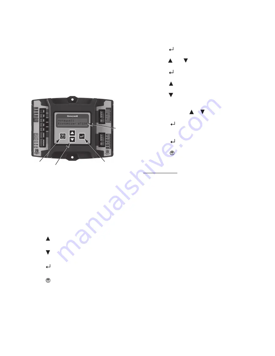
User Interface —
The user interface consists of a 2--line LCD display and a
4--button keypad on the front of the economizer controller.
2 LINE
LCD
MENU UP
(EXIT)
BUTTON
SCROLL
UP/DOWN
BUTTONS
SELECT
(ENTER)
BUTTON
C11548
Fig. 53 -- W7220 Controller
Keypad —
The four navigation buttons (see Fig. 53) are used to scroll
through the menus and menu items, select menu items,
and to change parameter and configuration settings.
Using the Keypad with Menus —
To use the keypad when working with menus:
S
Press the
(Up arrow) button to move to the previous
menu.
S
Press the
(Down arrow) button to move to the next
menu.
S
Press the
(Enter) button to display the first item in
the currently displayed menu.
S
Press the
(Menu Up/Exit) button to exit a menu’s
item and return to the list of menus.
The Menus in display order are:
S
STATUS
S
SETPOINTS
S
SYSTEM SETUP
S
ADVANCED SETUP
S
CHECKOUT
S
ALARMS
Using the Keypad with Settings and Parameters —
To use the keypad when working with Setpoints, System
and Advanced Settings, Checkout tests and Alarms:
3. Navigate to the desired menu.
4. Press the
(Enter) button to display the first item in
the currently displayed menu.
5. Use the
and
buttons to scroll to the desired
parameter.
6. Press the
(Enter) button to display the value of the
currently displayed item.
7. Press the
button to increase (change) the displayed
parameter value.
8. Press the
button to decrease (change) the displayed
parameter value.
NOTE
: When values are displayed, pressing and
holding the
or
button causes the
display to automatically increment.
9. Press the
(Enter) button to accept the displayed
value and store it in nonvolatile RAM.
10. “CHANGE STORED” displays.
11. Press the
(Enter) button to return to the current
menu parameter.
12. Press the
(Menu Up/Exit) button to return to the
previous menu.
Menu Structure
IMPORTANT
: Table 9 illustrates the complete hierarchy.
Your menu parameters may be different depending on your
configuration. For example if you do not have a DCV (CO
2
)
sensor, then none of the DCV parameters appear.
The menu hierarchy has been modified to reflect controller
configuration for 2--speed indoor fan application in the
Staged Air Volume option.
NOTE
: Some parameters in the menus use the letters MA
or MAT, indicating a mixed air temperature sensor
location before the cooling coil. This unit application has
the control sensor located after the cooling coil, in the fan
section, where it is designated as (Cooling) Supply Air
Temperature or SAT sensor.
Содержание 50LC 07
Страница 9: ...9 COOLING CHARGING CHARTS C150169 Fig 9 Cooling Charging Charts 07 ...
Страница 10: ...10 COOLING CHARGING CHARTS C150172 Fig 10 Cooling Charging Charts 08 ...
Страница 11: ...11 COOLING CHARGING CHARTS C150170 Fig 11 Cooling Charging Charts 09 ...
Страница 12: ...12 COOLING CHARGING CHARTS C150171 Fig 12 Cooling Charging Charts 12 ...
Страница 27: ...27 C150181 Fig 34 50LC 07 Control Wiring Diagram ...
Страница 28: ...28 C150225 Fig 35 50LC 07 RTU Open Control Wiring Diagram ...
Страница 29: ...29 C14095 Fig 36 50LC 07 Power Wiring Diagram 208 230V 460V and 575V Units ...
Страница 30: ...30 C14013 Fig 37 50LC 08 12 Control Wiring Diagram ...
Страница 31: ...31 C14104 Fig 38 50LC 08 12 RTU Open Control Wiring Diagram ...
Страница 32: ...32 C14105 Fig 39 50LC 08 12 Power Wiring Diagram 208 230V Units ...
Страница 33: ...33 C150216 Fig 40 50LC 08 12 Power Wiring Diagram 460V 575V Units ...
Страница 57: ...57 C13683 Fig 62 Typical EconoMi er X Wiring Diagram ...