


23
2. Check the sensor’s cover. If it is loose or missing,
secure the cover to the sensor housing.
3. Replace sensor assembly.
Sensor’s Power LED is Off
1. Check the controller’s Power LED. If it is off,
determine why the controller does not have power
and make the necessary repairs.
2. Check the wiring between the sensor and the
controller. If wiring is loose or missing, repair or
replace as required.
Controller’s Power LED is Off
1. Make sure the circuit supplying power to the
controller is operational. If not, make sure JP2 and
JP3 are set correctly on the controller before applying
power.
2. Verify that power is applied to the controller’s supply
input terminals. If power is not present, replace or
repair wiring as required.
Remote Test/Reset Station’s Trouble LED Does Not
Flash When Performing a Dirty Test, But the
Controller’s Trouble LED Does
1. Verify that the remote test/station is wired as shown
in Fig. 25. Repair or replace loose or missing wiring.
2. Configure the sensor dirty test to activate the
controller’s supervision relay. See “Changing sensor
dirty test operation.”
Sensor’s Trouble LED is On, But the Controller’s
Trouble LED is OFF
Remove JP1 on the controller.
PROTECTIVE DEVICES
Compressor Protection
Overcurrent
Each compressor has internal linebreak motor protection.
Reset is automatic after compressor motor has cooled.
Overtemperature
Each compressor has an internal protector to protect it
against excessively high discharge gas temperatures. Reset
is automatic.
High Pressure Switch
Each system is provided with a high pressure switch
mounted on the discharge line. The switch is
stem--mounted and brazed into the discharge tube. Trip
setting is 630 psig +/-- 10 psig (4344 +/-- 69 kPa) when
hot. Reset is automatic at 505 psig (3482 kPa).
Low Pressure Switch
Each system is protected against a loss of charge and low
evaporator coil loading condition by a low pressure switch
located on the suction line near the compressor. The
switch is stem--mounted. Trip setting is 54 psig +/-- 5 psig
(372 +/-- 34 kPa). Reset is automatic at 117 +/-- 5 psig
(807 +/-- 34 kPa).
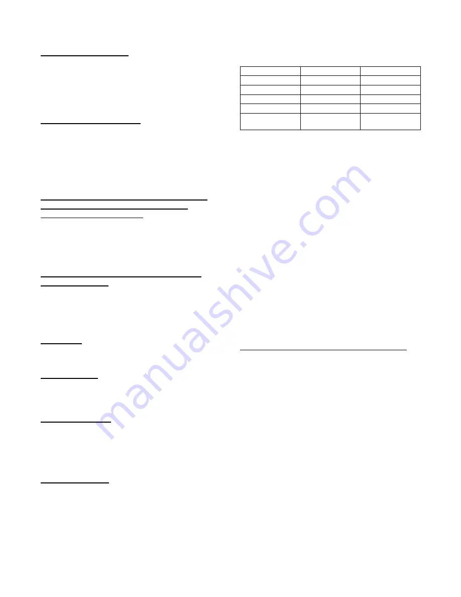
Supply (Indoor) Fan Motor Protection
Disconnect and lockout power when servicing fan motor.
The supply fan motor is equipped with an overcurrent
protection device. The type of device depends on the
motor size. (See Table 4.)
Table 4 – Supply Fan Motor Protection Devices
Motor Size (bhp)
Overload Device
Reset
1.7
Internal linebreak
Automatic
2.4
Internal linebreak
Automatic
2.9
Thermik
Automatic
3.7
Thermik
Automatic
5.2
External (circuit
breaker)
Manual
The Internal Linebreak type is an imbedded switch that
senses both motor current and internal motor temperature.
When this switch reaches its trip setpoint, the switch
opens the power supply to the motor and the motor stops.
Reset is automatic when the motor windings cool down.
The Thermik device is a snap--action overtemperature
protection device that is imbedded in the motor windings.
It is a pilot--circuit device that is wired into the unit’s 24--v
control circuit. When this switch reaches its trip setpoint,
it opens the 24--v control circuit and causes all unit
operation to cease. This device resets automatically when
the motor windings cool. Do not bypass this switch to
correct trouble. Determine the cause and correct it.
The
External
motor
overload
device
is
a
specially--calibrated circuit breaker that is UL recognized
as a motor overload controller.
It is an overcurrent
device. When the motor current exceeds the circuit
breaker setpoint, the device opens all motor power leads
and the motor shuts down. Reset requires a manual reset
at the overload switch. This device (designated IFCB) is
located on the side of the supply fan housing, behind the
fan access panel.
Troubleshooting Supply Fan Motor Overload Trips
The supply fan used in 50LC units is a forward--curved
centrifugal wheel. At a constant wheel speed, this wheel
has a characteristic that causes the fan shaft load to
DECREASE when the static pressure in the unit--duct
system increases and to INCREASE when the static
pressure in the unit--duct system decreases (and fan
airflow rate increases). Motor overload conditions
typically develop when the unit is operated with an access
panel removed, with unfinished duct work, in an
economizer--open mode, or a leak develops in the duct
system that allows a bypass back to unit return opening.
Condenser Fan Motor Protection
The condenser fan motors are internally protected against
overtemperature.
Control Circuit, 24--V
The control circuit is protected against overcurrent
conditions by a circuit breaker mounted on control
transformer TRAN. Reset is manual.
Содержание 50LC 07
Страница 9: ...9 COOLING CHARGING CHARTS C150169 Fig 9 Cooling Charging Charts 07 ...
Страница 10: ...10 COOLING CHARGING CHARTS C150172 Fig 10 Cooling Charging Charts 08 ...
Страница 11: ...11 COOLING CHARGING CHARTS C150170 Fig 11 Cooling Charging Charts 09 ...
Страница 12: ...12 COOLING CHARGING CHARTS C150171 Fig 12 Cooling Charging Charts 12 ...
Страница 27: ...27 C150181 Fig 34 50LC 07 Control Wiring Diagram ...
Страница 28: ...28 C150225 Fig 35 50LC 07 RTU Open Control Wiring Diagram ...
Страница 29: ...29 C14095 Fig 36 50LC 07 Power Wiring Diagram 208 230V 460V and 575V Units ...
Страница 30: ...30 C14013 Fig 37 50LC 08 12 Control Wiring Diagram ...
Страница 31: ...31 C14104 Fig 38 50LC 08 12 RTU Open Control Wiring Diagram ...
Страница 32: ...32 C14105 Fig 39 50LC 08 12 Power Wiring Diagram 208 230V Units ...
Страница 33: ...33 C150216 Fig 40 50LC 08 12 Power Wiring Diagram 460V 575V Units ...
Страница 57: ...57 C13683 Fig 62 Typical EconoMi er X Wiring Diagram ...