


Model 601GAS burner — Instruction manual
MN601GAS 012516
– 25 –
Where appliance instructions differ from this manual, follow the appliance instructions.
7. Troubleshooting
(continued)
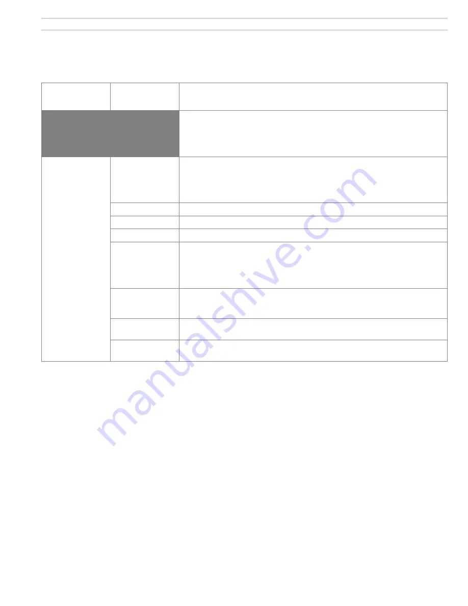
Problem
Possible
cause
Corrective action
WARNING
These procedures must only be performed by a qualified service technician. Use care
when performing tests on electrically or mechanically live parts. Disconnect power to
burner/appliance and close main manual gas valve when removing components for ser-
vice. Failure to comply could result in severe personal injury, death or substantial property
damage.
Burner lights, but
locks out after TFI
Insufficient flame
signal
Flame rod may be touching ground, insulator may be broken, or contamination may cause
a path to ground. Inspect and clean if necessary. See page 11 for more information.
Check the flame rod position in burner per page 11. Adjust if necessary. The flame rod
must be correctly positioned for best flame signal.
Airflow
Check air damper setting against Table 1a, page 9.
Orifice size
Check gas orifice size. See Table 1a, page 9.
Manifold pressure
Check gas manifold pressure — should be between 3.2 and 3.8 inches w.c., unless specified
Low gas supply
pressure
Check line pressure at gas train entrance. Gas pressure must be at least 5 inches w.c. —
If other appliances are on the same line or regulator, and burner pressure drops when they
are on, the line is undersized. Contact your gas supplier.
If gas pressure is always low, check the supply regulator setting and adjust if necessary.
Inlet gas pressure must not exceed 14 inches w.c.
Improper draft
Over-fire draft should not be higher than specified in the appliance manufacturer's instruc-
tions. Follow the appliance manual instructions to troubleshoot excess overfire pressure or
poor draft problems if necessary.
Flame rod grounded
Check flame rod and insulator. If the flame rod is grounded in any way, the control will lock-
out after the trial for ignition.
120
VAC
polarity
Check the power supply polarity. If hot and neutral wires are reversed, the flame rod circuit
cannot sense flame correctly. The 60200FR control will lockout after the trial for ignition.
60200FR must display 0.8 microamps. Check following if signal is lower.