Carlin 601GAS Скачать руководство пользователя страница 21

Model 601GAS burner — Instruction manual

MN601GAS  012516

– 21 –

Where appliance instructions differ from this manual, follow the appliance instructions.

Installer/servicer

Please check off and fill in certificate

 After completing start-up and testing or service, fill out the certificate 

on page 30.

  Should overheating or an emergency occur, immediately:


•  Shut off main manual gas valve.


•  Shut off control switch to burner.


Under some circumstances power should remain on for 

circulating blowers or other equipment. Determine proper 

response before attempting start-up. If appliance fails igni-

tion on several attempts, close gas valve and use burner 

blower to purge appliance before restart.

5.  Perform checkout procedures   •   fill out certificate

Make final burner adjustments 

(continued)

Inspect flame

 Look at flame through appliance observation port. The flame should 

be a soft blue with well-defined orange and yellow tips for natural gas, 

or well-defined yellow tips for propane gas. (If you make air or gas 

pressure changes later, inspect the flame again.)

Check the firing rate

 Natural gas only — Turn off all other gas appliances connected to 

the gas meter. Use a stopwatch to time the number of seconds for a 

flow of one cubic foot of gas (two revolutions for a one half cubic foot 

per revolution dial, for example). You will also need to know the gas 

heat content in Btu per cubic foot. Determine the actual input from:  

INPUT = (3600 x Btu per cubic foot) ÷ (number of seconds for one 

cubic foot), for firing rate in Btuh. For example, for 1050 Btu per cubic 

foot natural gas, with meter timed at 15.1 seconds for one cubic foot 

of gas: INPUT example = (3600 x 1050) ÷ (15.1) = 250,500 Btuh. 

Firing rate should be within ± 5% of rated input for the appliance. 

Adjust the gas pressure regulator if necessary to obtain the correct 

firing rate. Valve outlet pressure must not be lower than 3.2 inches 

w.c. nor higher than 3.8 inches w.c.

  For propane gas, contact your propane supply for procedure to verify 

firing rate.

Preparation before checkout

 Burner/appliance installed per appliance instruction manual?

 Burner components/settings verified against Table 1a, page 9?

 Burner/appliance installed per all applicable codes?

  Installation site has adequate ventilation openings and vent system?

 Gas supply line in good condition and sized correctly?

 All gas line joints sealed with pipe dope listed for use with liquefied 

petroleum gases?

 Gas supply pressure to gas valves checked?

 Regulator installed if pressure can exceed 14 inches w.c.? 

 Air purged from gas line?

 Gas piping checked for leaks?

 Wiring installed per burner manual  and appliance instructions?

 Burner inspected and primary control flame failure lockout checked?

 Start-up sequence performed (page 16)?

Make final burner adjustments

Check for leaks in gas piping

  Smell around burner to make sure there is no gas leak in near-burner 

piping. Verify integrity of gas line joints between gas valves and burner 

gas inlet connection using soap suds mixture.

Check/adjust gas valve outlet pressure

 With burner running, check manometer reading for gas valve outlet 

pressure. Adjust regulator if necessary so the reading is 3.5 inches 

w.c. for either natural gas or propane gas.

Check combustion using instruments


Do not attempt to confirm combustion simply 

by inspecting the flame visually. You must use 

combustion test instruments.

 Failure to properly 

verify/adjust combustion could allow unsafe operation of 

the burner, resulting in severe personal injury, death or 

substantial property damage.
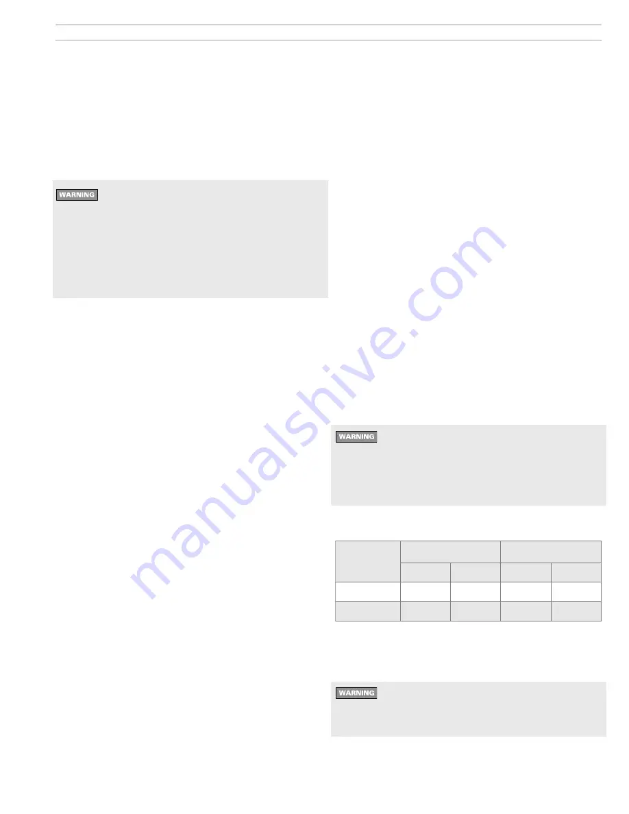
 Insert a test probe into appliance vent outlet to sample flue products. 

The results should show CO

2

 or O

2

 as follows:

Fuel

CO

2

O

2

Minimum Maximum Maximum Minimum

Natural Gas

8.5%

10.0%

6.2%

3.5%

Propane Gas

9.5%

11.2%

6.0%

3.5%

 If the combustion results are outside the range above, and the firing 

rate of the burner is within 5% of rated input, open or close the air 

damper until the CO

2

 (or O

2

) are acceptable.

  After CO

2

 (O

2

) tests are completed satisfactorily, measure 

flue products for carbon monoxide (CO) concentration. The 

CO must not exceed 50 ppm adjust to “air free”, or other if 

specified by local codes.

 Check overfire pressure in the appliance. Refer to the appliance 

manual for recommended reading and barometric damper instructions 

for proper setting of damper, when used.

Содержание 601GAS

Страница 1: ...pply pressure 5 inches w c Manifold pressure 3 5 inches w c Electrical Power 120V 60 Hz 1 Phase Motor Marathon PSC 1 2 HP 3450 RPM 8 4 amps Total Current Approx less than 10 amps Ignition Carlin Model...

Страница 2: ...Model 601GAS burner Instruction manual MN601GAS 012516 2 Where appliance instructions differ from this manual follow the appliance instructions...

Страница 3: ...husetts require a nonre cycle primary control and gas train Make sure the burner is properly equipped for Massachusetts installations United States installations Burner appliance installations in the...

Страница 4: ...d burner flange door for access and removal of combustion head gas manifold assembly 10 Ignitor Carlin Model 41000 solid state electronic ignitor 14 000 volts continuous duty rated 11 Hinged cover pla...

Страница 5: ...01GAS 012516 5 Where appliance instructions differ from this manual follow the appliance instructions 601GAS burner at a glance ITEM 17 MassachusettsCodeburnersalsoinclude an 8 second time delay relay...

Страница 6: ...hat has one or more sides exposed to the outside Install a listed stainless steel liner to vent the flue products A defective vent system could result in severe personal injury death or substantial pr...

Страница 7: ...tion manual when available to size combustion air openings Use the following guidelines when appliance instructions are not available All air from inside building building must be well ventilated Size...

Страница 8: ...s chamber liners may contain carcinogenic particles chrystobalites after exposure to heat Airborne particles from fiberglass or ceramic fiber components have been listed as potentially carcinogenic by...

Страница 9: ...NA 31 32 9687 21 32 6562 5 5 1 350 000 NA NA NA NA NA NA 1 1 000 11 16 6875 6 1 400 000 NA NA NA NA NA NA 1 1 16 1 063 23 32 7187 6 5 1 450 000 NA NA NA NA NA NA 1 1 8 1 125 3 4 7500 8 75 1 500 000 N...

Страница 10: ...ir tube insertion length Btuh L W C L H VC Dry Wet Dry Wet Dry Wet Wet Dry Wet 700 000 18 22 16 18 7 5 8 5 19 16 22 Welded flange Burners with welded flange have fixed usable tube length UTL set for t...

Страница 11: ...proceeding b Close the manual gas valve on the gas supply line c Disconnect the burner gas train union d Remove the gas pipe at the burner air tube e Remove the four nuts securing the burner hinged do...

Страница 12: ...in J box b See the label in the burner junction box or the wiring diagram on page 15 Gas valve vent opening If local codes require install piping from vent connection to outside sized and installed pe...

Страница 13: ...y pressure 5 inches w c Do not expose the gas train to gas pressure in excess of 14 inches water column Higher pressure could damage the valve seat resulting in potentially hazardous condition When pr...

Страница 14: ...roximately Approximate amp draw Motor 1 2 HP During ignition Add 0 5 amps to steady current below Steady operation Carlin motor 5 2 AMPS Marathon motor 8 4 amps 2 The 120 vac power connections to the...

Страница 15: ...nstructions differ from this manual follow the appliance instructions Figure 11 Wiring diagrams 601GAS burner with 60200FR primary control typical Standard Commercial Gas Train 120V Ventless Commercia...

Страница 16: ...joints near burner and check for any leaks If any leaks appear repair before proceeding and retest Set burner air damper See Figure 12 Loosen air damper locking nut Then rotate the ajustment screw un...

Страница 17: ...eset control from Latch up Press for 30 second Display Control ESC Display previous Operating State from Operating screen Exit Log or Setup screen to Operating screen with 3 second press Scroll throug...

Страница 18: ...n TFI or Post purge Motor ignitor or valve relay weld detected If the control is miswired causing voltage to be detected on the outputs terminals motor ignitor or valve when not ex pected Recycle limi...

Страница 19: ...urrent causes the cycle to be faulted Recycle Yes if a recycle occurred in CFH cycle A recycle causes the cycle to be faulted No Run time Time motor output is on during this cycle Burn time Time valve...

Страница 20: ...ac Check all electrical connections Control is in lockout Press the reset button for 1 second Other no start problems Line voltage 90 VAC Check line voltage 132VAC Motor relay welded If valve ignitor...

Страница 21: ...per appliance instruction manual Burner components settings verified against Table 1a page 9 Burner appliance installed per all applicable codes Installation site has adequate ventilation openings and...

Страница 22: ...the manifold gas pressure with the manometer Set the high gas pressure switch to a pressure less than actual manifold pressure The high gas pressure switch should shut the burner down Replace the swi...

Страница 23: ...erform the complete checkout procedures of pages 16 through 22 including system inspection and checks 6 Maintenance and service procedures Maintenance service procedures Cleaning blower wheel 1 The bl...

Страница 24: ...e door is closed securely and that door switch is closed Gas pressure Check low gas pressure switch If it is open gas supply may be too low or no gas flow check supply line and manual valves Gas train...

Страница 25: ...ifice size Check gas orifice size See Table 1a page 9 Manifold pressure Check gas manifold pressure should be between 3 2 and 3 8 inches w c unless specified Low gas supply pressure Check line pressur...

Страница 26: ...9147 99427 9a Static disc Built into 1x and 2x heads non removable not used in 3x heads NA 9b Diffuser plate 1x heads only 99162 Combustion head assemblies 11 combustion head assembly includes items s...

Страница 27: ...follow the appliance instructions 8 Replacement parts Burner continued Set screws Combustion head assembly Burnerisshownwithweldedflange suppliedonlyonburners ordered for specific appliance applicatio...

Страница 28: ...surized firing Failure to comply could result in severe personal injury death or substantial property damage When using a welded flange burner verify the insertion depth on the appliance and burner se...

Страница 29: ...Model 601GAS burner Instruction manual MN601GAS 012516 29 Where appliance instructions differ from this manual follow the appliance instructions...

Страница 30: ...model Serial number Measured firing rate Btuh Gas orifice drill size Manifold gas pressure IWC Inlet gas pressure IWC r p r o l a r u t a n l e u F 2 O 2 O C opane Were controls tested Comments about...

Отзывы: