Carlin 601GAS Скачать руководство пользователя страница 17

Model 601GAS burner — Instruction manual

MN601GAS  012516

– 17 –

Where appliance instructions differ from this manual, follow the appliance instructions.

4.  Check System   •   Start-up Burner/Appliance 

(continued)

Programming and Setup – 60200FR 

Definitions:

Call for Heat (C.F.H.): TT on + Limit In on + BV on + CO on 
Pre-Purge: Time period the motor is on prior to T.F.I.
Trial for Ignition: (T.F.I.): Burner Flame Establishing period
Post-Purge: Time period the motor is on after a Call for Heat has been satisfied
Post-Purge Interrupt: If selected is Time at which the 120 second Post-purge will be interrupted if a C.F.H. occurs during the Post-purge.
Allowed Recycles: Number of Recycles allowed during a single C.F.H. prior to lockout due to flame loss.
TT Used: Select “NO” when not using TT, select “YES” when using TT 
Baseline Reset: Resets the baseline statistics used by the fault history
Factory Default: Resets ALL settings to the “Factory Defaults”


Do not start the burner if the combustion chamber contains gas.

Button Functions – 60200FR

Reset
1. Return to Standby from other operating states. Press for ½ second
2. Reset control from Lockout. Press for 1 second
3. Reset control from Latch-up. Press for 30 second

Display Control
ESC
 / 

Display previous Operating State from Operating screen.
Exit Log or Setup screen to Operating screen with 3 second press.
Scroll through recent fault in Log screen.
Scroll to previous parameter in Setup screen.
Reject parameter change from Setup screen. Displays 

Unchanged 

on line 2 then after 2 sec, displays parameter with unchanged 

value.

DN / 

Display Time on line 2 of Operating screen.
Scroll down when in Log or Setup screen.

UP

 / 

Display Flame Rod – µAmps on line 2 of Operating screen.
Scroll up when in Log or Setup screen.

ENTR

 / 

Display status/fault messages on line 2 from Operating screen.
Move to less recent fault in Log screen.
Move to next parameter in Setup screen.
Accept parameter change from Setup screen. Displays 

Entered

 on 

line 2 then after 2 sec, displays parameter with changed value.

UP 

/


 & ENTR 

 for 3 seconds 

Enter Setup screen.

DN 

/


 & ENTR 

 for 3 seconds 

Enter Fault History screen.

DN 

/


 & 

UP

 / 

 for 3 seconds 

Enter Diagnostic screen to display Load Current sensed and Line 

voltage.

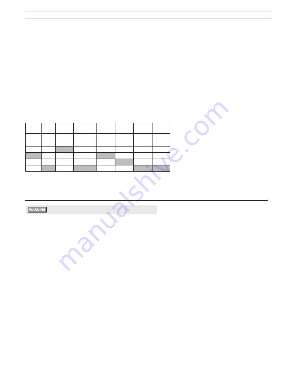
Shaded box = default settings     

*In seconds    

MA code (“N” models) are non-recycling and will lock out on flame failure

Pre-

Purge*

T.F.I.*

Post-

Purge*

Post-Purge

Interrupt*

Allowed

Recycles

TT Used

Reset

Baseline

Factory

Default

120

60

90

30

30

15

3

10

6

10

60

1

Yes

Yes

Yes

0

4

0

Never

None

No

No

No

Содержание 601GAS

Страница 1: ...pply pressure 5 inches w c Manifold pressure 3 5 inches w c Electrical Power 120V 60 Hz 1 Phase Motor Marathon PSC 1 2 HP 3450 RPM 8 4 amps Total Current Approx less than 10 amps Ignition Carlin Model...

Страница 2: ...Model 601GAS burner Instruction manual MN601GAS 012516 2 Where appliance instructions differ from this manual follow the appliance instructions...

Страница 3: ...husetts require a nonre cycle primary control and gas train Make sure the burner is properly equipped for Massachusetts installations United States installations Burner appliance installations in the...

Страница 4: ...d burner flange door for access and removal of combustion head gas manifold assembly 10 Ignitor Carlin Model 41000 solid state electronic ignitor 14 000 volts continuous duty rated 11 Hinged cover pla...

Страница 5: ...01GAS 012516 5 Where appliance instructions differ from this manual follow the appliance instructions 601GAS burner at a glance ITEM 17 MassachusettsCodeburnersalsoinclude an 8 second time delay relay...

Страница 6: ...hat has one or more sides exposed to the outside Install a listed stainless steel liner to vent the flue products A defective vent system could result in severe personal injury death or substantial pr...

Страница 7: ...tion manual when available to size combustion air openings Use the following guidelines when appliance instructions are not available All air from inside building building must be well ventilated Size...

Страница 8: ...s chamber liners may contain carcinogenic particles chrystobalites after exposure to heat Airborne particles from fiberglass or ceramic fiber components have been listed as potentially carcinogenic by...

Страница 9: ...NA 31 32 9687 21 32 6562 5 5 1 350 000 NA NA NA NA NA NA 1 1 000 11 16 6875 6 1 400 000 NA NA NA NA NA NA 1 1 16 1 063 23 32 7187 6 5 1 450 000 NA NA NA NA NA NA 1 1 8 1 125 3 4 7500 8 75 1 500 000 N...

Страница 10: ...ir tube insertion length Btuh L W C L H VC Dry Wet Dry Wet Dry Wet Wet Dry Wet 700 000 18 22 16 18 7 5 8 5 19 16 22 Welded flange Burners with welded flange have fixed usable tube length UTL set for t...

Страница 11: ...proceeding b Close the manual gas valve on the gas supply line c Disconnect the burner gas train union d Remove the gas pipe at the burner air tube e Remove the four nuts securing the burner hinged do...

Страница 12: ...in J box b See the label in the burner junction box or the wiring diagram on page 15 Gas valve vent opening If local codes require install piping from vent connection to outside sized and installed pe...

Страница 13: ...y pressure 5 inches w c Do not expose the gas train to gas pressure in excess of 14 inches water column Higher pressure could damage the valve seat resulting in potentially hazardous condition When pr...

Страница 14: ...roximately Approximate amp draw Motor 1 2 HP During ignition Add 0 5 amps to steady current below Steady operation Carlin motor 5 2 AMPS Marathon motor 8 4 amps 2 The 120 vac power connections to the...

Страница 15: ...nstructions differ from this manual follow the appliance instructions Figure 11 Wiring diagrams 601GAS burner with 60200FR primary control typical Standard Commercial Gas Train 120V Ventless Commercia...

Страница 16: ...joints near burner and check for any leaks If any leaks appear repair before proceeding and retest Set burner air damper See Figure 12 Loosen air damper locking nut Then rotate the ajustment screw un...

Страница 17: ...eset control from Latch up Press for 30 second Display Control ESC Display previous Operating State from Operating screen Exit Log or Setup screen to Operating screen with 3 second press Scroll throug...

Страница 18: ...n TFI or Post purge Motor ignitor or valve relay weld detected If the control is miswired causing voltage to be detected on the outputs terminals motor ignitor or valve when not ex pected Recycle limi...

Страница 19: ...urrent causes the cycle to be faulted Recycle Yes if a recycle occurred in CFH cycle A recycle causes the cycle to be faulted No Run time Time motor output is on during this cycle Burn time Time valve...

Страница 20: ...ac Check all electrical connections Control is in lockout Press the reset button for 1 second Other no start problems Line voltage 90 VAC Check line voltage 132VAC Motor relay welded If valve ignitor...

Страница 21: ...per appliance instruction manual Burner components settings verified against Table 1a page 9 Burner appliance installed per all applicable codes Installation site has adequate ventilation openings and...

Страница 22: ...the manifold gas pressure with the manometer Set the high gas pressure switch to a pressure less than actual manifold pressure The high gas pressure switch should shut the burner down Replace the swi...

Страница 23: ...erform the complete checkout procedures of pages 16 through 22 including system inspection and checks 6 Maintenance and service procedures Maintenance service procedures Cleaning blower wheel 1 The bl...

Страница 24: ...e door is closed securely and that door switch is closed Gas pressure Check low gas pressure switch If it is open gas supply may be too low or no gas flow check supply line and manual valves Gas train...

Страница 25: ...ifice size Check gas orifice size See Table 1a page 9 Manifold pressure Check gas manifold pressure should be between 3 2 and 3 8 inches w c unless specified Low gas supply pressure Check line pressur...

Страница 26: ...9147 99427 9a Static disc Built into 1x and 2x heads non removable not used in 3x heads NA 9b Diffuser plate 1x heads only 99162 Combustion head assemblies 11 combustion head assembly includes items s...

Страница 27: ...follow the appliance instructions 8 Replacement parts Burner continued Set screws Combustion head assembly Burnerisshownwithweldedflange suppliedonlyonburners ordered for specific appliance applicatio...

Страница 28: ...surized firing Failure to comply could result in severe personal injury death or substantial property damage When using a welded flange burner verify the insertion depth on the appliance and burner se...

Страница 29: ...Model 601GAS burner Instruction manual MN601GAS 012516 29 Where appliance instructions differ from this manual follow the appliance instructions...

Страница 30: ...model Serial number Measured firing rate Btuh Gas orifice drill size Manifold gas pressure IWC Inlet gas pressure IWC r p r o l a r u t a n l e u F 2 O 2 O C opane Were controls tested Comments about...

Отзывы: