14
ENG
“optiMist” +0300065EN - rel. 1.6 - 18/06/2021
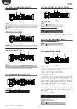
3. ELECTRICAL CONNECTIONS
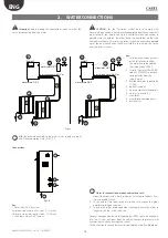
3.1 Wiring inlets
1
2
Fig. 3.a
1.
power supply
2.
control terminal block
3.2 Power supply
Depending on the model:
•
EC*******0 voltage 230Vac 50Hz
•
EC*******U voltage 230Vac 60Hz
N L
230 Vac
PE
Fig. 3.b
Important:
The cables must conform to local standards.
Install a power switch outside the humidifier to completely isolate
the mains power supply, with earth (fault protection 30 mA) the earth
cable must be mechanically protected and not exposed. The unit is
not compatible with IT power supply systems. The single-pole current
breaking switch must be fitted upstream of the device.
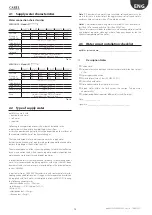
3.3 Connections to the pCO
The connections listed below are to be made directly to the pCO
terminals.
J2 B1 Main humidification/winter (DEC) control probe
B2 Humidification/winter (DEC) limit probe
B3 Recovery activation (IEC) configurable analogue signal
J3 B5 AUX temperature probe (only NTC or PT100)
J4 Y1 0-10V signal output for controlling another cabinet
J6 B6 Main evaporative cooling/summer (IEC) control probe
B7 Evaporative cooling/summer (IEC) limit probe
Tab. 3.a
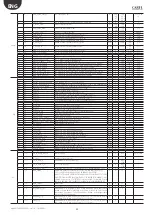
3.4 Connections to the terminal board.
PEN/GO
Pump / On-Off remote enabling
DEC/GO
Humidification control signals from external voltage-free
contact, humidistat type ON/OFF
IEC/GO
Evaporative cooling control signals from external voltage-free
contact, thermostat type ON/OFF
PR/GO
Humidification/winter or evaporative cooling/summer priority
REC/GO
Recovery activation (IEC) signal, type ON/OFF
ROAL/GO Water treatment system alarm signal
ROW/GO Water treatment system anomaly signal
BKUP/GO Backup cabinet signal
FLUX/GO Air flow switch
SC/GO
Droplet separator clogging signal from differential pressure switch
RWL/GO Not used
AF/AF
Antifreeze activation output
HBT/HBT Sign of life, this cabinet
RWP/GO Not used
ROEN/GO Water treatment system control
AL/AL
Cumulative alarm relay output
NO1/GO Solenoid valve (optional) step 1
NO2/GO Solenoid valve (optional) step 2
Tab. 3.b
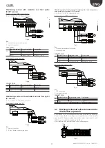
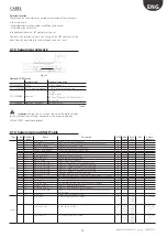
Remoto ON/OFF
Cables
• up to 30 m: two-wire cable AWG20/22
electrical specifications for the contact voltage-free contact
PEN
G0
Fig. 3.c
Key:
Remote pump ON/OFF
CONNECTIONS
Cabinet
Remote ON/OFF
PEN (pump enabling)
NC/NO
G0A
COM
Please Note: the unit is supplied with jumpers on the PEN-G0A
contacts.
Содержание optiMist EC005 0 Series
Страница 1: ...optiMist NO POWER SIGNAL CABLES TOGETHER READ CAREFULLY IN THE TEXT User manual evaporative cooling ...
Страница 2: ......
Страница 4: ......
Страница 6: ......
Страница 45: ......


