35
ENG
“optiMist” +0300065EN - rel. 1.6 - 18/06/2021
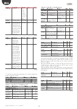
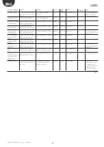
Configuration of the control inputs for the zone dedicated to
humidification is done through the following screens.
Display
Description
Range
Def. UoM
Config.Inputs 2/8
HUMIDIFICATION
Operation
type:
Set control type
Humidity
HLimit Humid.
HTemp. Limit
External prop.Signal
Prop.+Humid.Lim. Sign.
Prop.+Temp.Lim.Sign.
Contact On/Off Cont.On/
Off+Hum.Lim Cont.On/
Off+Temp.Lim
Control
Signal
Type of control signal
[B1 analog inlet]
NTC, 0 to 135oh, 0-1V,
0-10V, 4-20mA,0-20mA
Min:
Minimum control
signal value
0 to 100
0
%rH/%
Max.
Maximum control
signal value
0 to 100
100 %rH/%
Offset:
Probe reading
correction offset
0 to 100
0
%rH/%
Tab. 8.u
Display Description
Range
Def.
UoM
Config.Inputs 3/8
HUMIDIFICATION
Limit
Type of control signal [B2
analog inlet]
NTC, 0...135oh, 0-1V,
0-10V, 4-20mA,
0-20mA
Min:
Minimum control signal
value
0…100%rH/
-20…70°C
0% rH /
-20°C
%rH/
°C-°F
Max:
Maximum control signal
value
0…100%rH/
-20…70°C
100%rH /
70°C
%rH/
°C-°F
Offset:
Probe reading correction
offset
0…100%rH/
-20…70°C
0
%rH/
°C-°F
Tab. 8.v
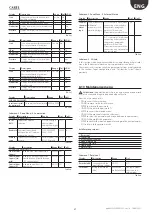
The configuration of the control inputs for the zone dedicated to
evaporative cooling (IEC) is done through the following screens.
Display
Description
Range
Def.
UoM
Config.Inputs 4/8
EVAPORATIVE COOLING
Operation
type:
Set control type
Temperature
Temp.+Humid. Limit
Temp.+Temp. Limit
Temp.+Flow Limit
Signal prop.external
Sign.prop+Humid.Lim.
Prop.+Temp.Lim.Sign.
Prop.+FlowLim.Sign.
Contact On/Off Cont.On/
Off+Humid.Lim. Cont.
On/Off+TempLim. Cont.
On/Off+FlowLim
External
prop.
sign.
Control
Signal
Type of control
signal [B6] analog
inlet]
NTC, 0 to 135oh, 0-1V,
0-10V, 4-20mA,0-20mA
0 to 10V
Min:
Minimum control
signal value
0 to 100% / -20°C to 70°C 0% /
-20°C
% /
°C-°F
Max:
Maximum control
signal value
0 to 100% / -20°C to 70°C 100% /
70°C
% /
°C-°F
Offset:
Probe reading
correction offset
0 to 100% / -20°C to 70°C 0
% /
°C-°F
Tab. 8.w
Display Description
Range
Def.
UoM
Config.Inputs 5/8
EVAPORATIVE COOLING
Limit
Type of limit signal [B7
analog inlet]
NTC, 0...135oh,
0-1V, 0-10V,
4-20mA,
0-20mA
Type
limit signal correspondence
(only if flow signal)
Air lock or Fan
Air lock
Min:
Minimum control signal
value
0…100%rH/
-20…70°C
0
% / %rH/
°C-°F
Max:
Maximum control signal
value
0…100%rH/
-20…70°C
100% - %rH
o 70°C
% / %rH/
°C-°F
Offset:
Probe reading correction
offset
0…100%rH/
-20…70°C
0
% / %rH/
°C-°F
Tab. 8.x
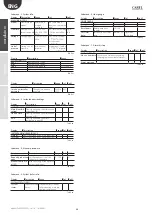
optiMist’s operation as an evaporative cooling (IEC) system requires the
indication of the activation of heat recovery. The next screen is dedicated
to setting that signal.
Display
Description
Range
Def.
UoM
Config.Inputs 6/8
EVAPORATIVE COOLING
Heat recovery
activation
from:
Recovery signal origin
selection
Digital or
analog input
or supervision
contact
Digital
contact
Min:
Minimum control
signal value
0 to 100%
0
%
Max:
Maximum control
signal value
0 to 100%
100
%
Offset:
Probe reading
correction offset
0 to 100%
0
%
Ist:
Hysteresis type
selection (ONLY
if analog input is
selected)
Direct or inverse direct
On:
Hysteresis activation
threshold (ONLY
if analog input is
selected)
0 to 99.9%
50
%
Off:
Hysteresis deactivation
threshold (ONLY
if analog input is
selected)
0 to 99.9
0
%
Tab. 8.y
Display
Description
Range
Def. UoM
Config.Inputs 7/8
TEMPERATURE CONTROL
P Factor:
proportional contribution reduction
factor
1..99
1
Integral
time:
integration time
1 to 32767 60
S
Tab. 8.z
A temperature probe can be installed just before the distribution system
in order to check that the temperature is optimal for correct absorption
of the atomised water.
Display
Description
Range
Def.
UOM
Enable
Enables temperature
measurement in the
atomisation zone.
When the temperature
drops below the “rack
temp. probe set point”,
a warning is displayed
Yes - No
NO
Содержание optiMist EC005 0 Series
Страница 1: ...optiMist NO POWER SIGNAL CABLES TOGETHER READ CAREFULLY IN THE TEXT User manual evaporative cooling ...
Страница 2: ......
Страница 4: ......
Страница 6: ......
Страница 45: ......


