39
ENG
“optiMist” +0300065EN - rel. 1.6 - 18/06/2021
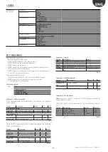
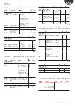
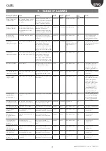
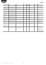
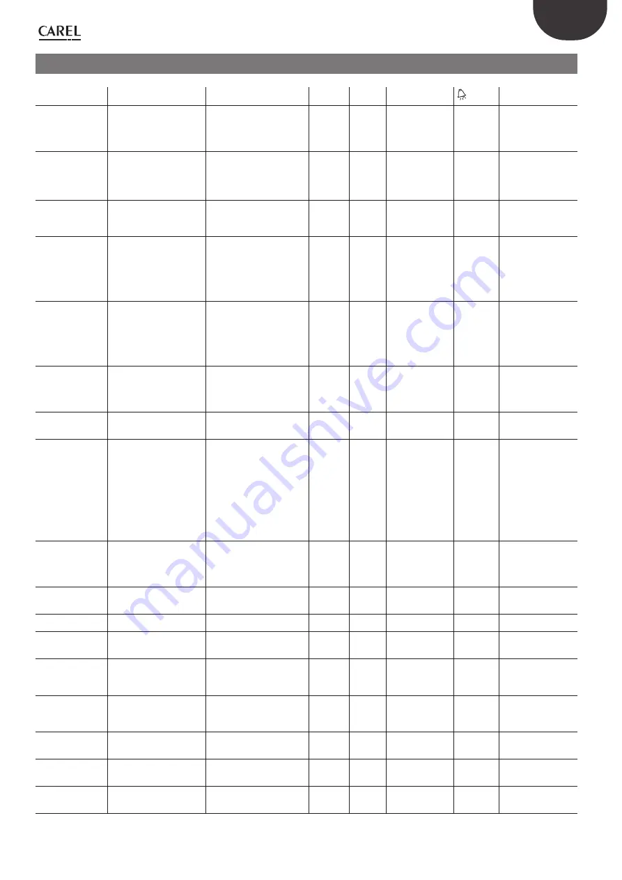
9. TABLE OF ALARMS
Message displayed
Cause
Solution
Reset
Alarm
status
Action
symbol
Notes
Water Treatment
System alarm
Dig. input Id6 open, check
any water
treatment unit
anomalies
Close dig. input ID6 with a
jumper, if the alarm disappears,
check the water treatment
system: if the alarm persists,
replace the controller
automatic active
stop production
on
Water Treatment
System warning
Digital input ID7 open/
closed (check logic): verify
water treatment system
anomaly
Close dig. input ID7 with
a jumper, if the alarm
disappears, check the water
treatment system: if the alarm
persists, replace the controller
automatic not active stop signalling
on
Inlet line low
pressure alarm
Low water pressure inlet
check supply circuit, water
supply pressure and if inlet filter
is clogged
automatic not active Stop production
on
check inlet pressure
three times before
generating next alarm
(LP Test)
High bypass
temperature alarm
excess water recirculation in
bypass
check operating temperature
(surrounding ambient air
and water); check that the
pressurised water distribution
system is not blocked so as to
cause water recirculation in the
pump.
automatic not active signal only +
opening of cabinet
drain valve for 10
s ?*
on
* make sure there is no
LP alarm from the probe
during these 10s.
High bypass
temperature alarm
excess water recirculation in
bypass, warning active for 60s
check operating temperature
(surrounding ambient air
and water); check that the
pressurised water distribution
system is not blocked so as to
cause water recirculation in the
pump
automatic active
Stop production
on
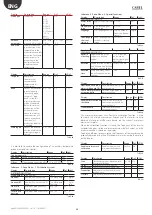
Inverter VFD alarm
inverter fault
check the status of the inverter
and replace if necessary
Note*
active
Stop production
on
* automatic reset on
the inverter control
depends on the type
of alarm, see chapter 7
inverter manual
Low pump cabinet
temperature alarm
water inlet temperature less
than 5°C
heat supply water or the
cabinet with a suitably rated
heater*
automatic active
Stop production
on
* possibility of activating
the defrost
Droplet separator
clogged alarm
droplet separator clogged
check the status of the droplet
separator(s)
manual
active
Stop production
on
* signal given by a
differential pressure switch
that sees an upstream-
downstream pressure
difference for the droplet
separator. When there
are 2 droplet separators
(HumidifIEC), 2
pressure switches will be
connected in series. P
selectable, delay selectable
High pressure
warning from
pressure probe
outlet pressure greater than
20 bars
check bypass valve calibration
automatic active
signal only
on
* before arriving at 20
base, the "Auto-tuning"
procedure causes the
system to operate at a
max of 15.5 bars.
Distribution system
maintenance request
warning
the flow-rate is 40% lower
in comparison to the MAX
production set.
The SW continues auto-tuning
automatically Check if the
distribution system is clogged
automatic not active signal only
on
Low pressure warning
from pressure probe
outlet pressure less than 1
Bar*
check tightness of outlet water
circuit
manual
active
Stop production
on
* threshold settable by
parameter
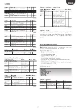
Pressure probe
broken or
disconnected alarm
pressure probe broken or
disconnected
check connection and
operation of the pressure probe
manual
active
Stop production
on
* active only if
configured
Main probe
(Humidification)
broken or
disconnected alarm
main probe disconnected or
broken
check connection and
operation of the main probe
manual
active
Stop production
on
* active only if
configured
Secondary probe
(Humidification)
broken or
disconnected alarm
secondary probe
disconnected or broken
check connection and
operation of the secondary
probe
manual
active
Stop production
on
* active only if
configured
Main probe
(IEC) broken or
disconnected alarm
main probe disconnected or
broken
check connection and
operation of the main probe
manual
active
Stop production
on
* active only if
configured
Secondary probe
(IEC) broken or
disconnected alarm
secondary probe
disconnected or broken
check connection and
operation of the secondary
probe
manual
active
Stop production
on
* active only if
configured
Auxiliary probe
broken or
disconnected alarm
auxiliary probe disconnected
or broken
check connection and
operation of the auxiliary probe
manual
not active signal only
on
* active only if
configured
Содержание optiMist EC005 0 Series
Страница 1: ...optiMist NO POWER SIGNAL CABLES TOGETHER READ CAREFULLY IN THE TEXT User manual evaporative cooling ...
Страница 2: ......
Страница 4: ......
Страница 6: ......
Страница 45: ......

