26
ENG
“optiMist” +0300065EN - rel. 1.6 - 18/06/2021
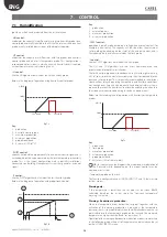
7. CONTROL
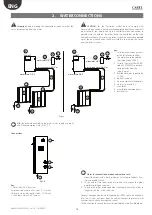
7.1 Humidification
lgorithms, which can be selected from the installer menu.
• HH control:
modulates the capacity (water flow-rate) using two humidity probes, one
control probe normally installed in the AHU in the return air, and one limit
probe, usually installed downstream of the droplet separator.
• HT control:
modulates the capacity (water flow-rate) with two probes, one humidity
control probe and one limit temperature probe. This configuration is
recommended for systems in which a certainly humidity level is required
without however excessively cooling the air.
• H control:
like the HH algorithm but without the limit humidity probe;
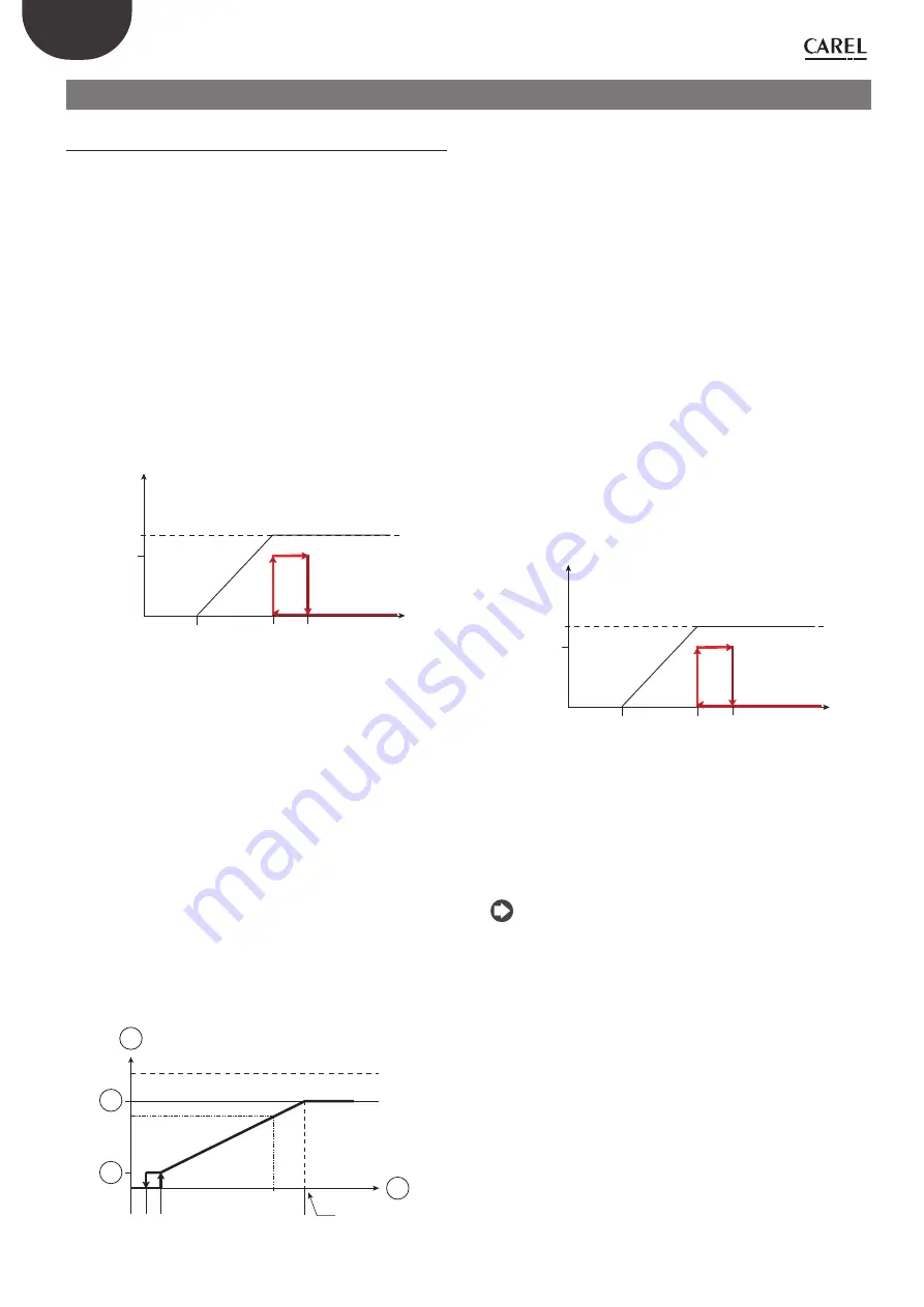
Below is the diagram of operation using humidity control probes
100%
Set + Diff
1
Set
Set - Band
% Rich.
T
Fig. 7.a
Key:
1.
production
2.
humidity control probe
3.
maximum production
4.
minimum production
5.
proportional band
6.
hysteresis (10% of “5”)
• PH/PT control:
capacity is modulated proportionally to an external control signal and is
limited based on the value measured by the limit temperature or humidity
probe. This is the typical configuration used in optiMist installations
connected to a Building Management System that generates a control
signal;
• P control:
like the PH/PT algorithm but without the limit humidity probe;
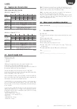
Below is the diagram of operation with proportional control.
100%
max
1
2
3
4
5% 5%
Fig. 7.b
Key:
1.
production
2.
external request
3.
maximum production
4.
minimum production
• CH/CT control:
operation in on/off mode, based on a voltage-free external contact (for
example, a humidistat). The capacity will thus be either the maximum
set or nothing, depending on the status of the external contact, and is
limited based on the value measured by the limit probe.
• C control:
like the CH/CT algorithm but without the limit probe;
The HH and TH algorithms are the most commonly-used, and
recommended for optiMist installations.
The limit humidity probe described above is usually set to high values, e.g.
80% rH, so as to limit the maximum moisture in the air introduced into the
duct and into the room. This is especially recommended in installations
where air flow-rate and operating, temperature and humidity conditions,
may change over time and, consequently an additional safety system is
required to prevent the humidifier from over-humidifying the air and, in
the worse case scenario, condensing in the ducts downstream.
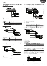
Below are the two diagrams of operation with humidity or temperature
probes
100%
Set + Diff
1
Set
Set - Band
% Rich.
T
Fig. 7.c
Key:
1.
production
2.
limit probe
3.
maximum production
4.
minimum production
5.
proportional band
6.
hysteresis (10% of the set point)
N.B.:
for convenience, the diagrams show continuous modulation of
the flow-rate while, depending on the model, control may be
continuous or in steps.
•
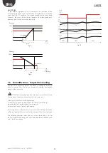
Temperature probe on the rack
The function, configurable under CONFIG. INPUTS 9 and 10, features two
distinct modes:
Warning only:
If the temperature is lower than the set point set on screen Bbc06,
calculated based on the system sizing, the “Low rack temperature”
warning is activated
W Reduction in production:
When the temperature drops below the set point, together with the
activation of the warning, production is reduced as the temperature
decreases, until it stops completely when the difference between the set
point referred to the temperature probe on the rack and the measured
temperature is higher than the “Band” set on screen 10.
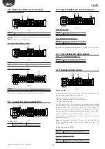
Operation of the warning and production reduction modes is summarised
in the following graph, where all of the parameters indicated can be set
on the CONFIG. INPUTS screen.
Содержание optiMist EC005 0 Series
Страница 1: ...optiMist NO POWER SIGNAL CABLES TOGETHER READ CAREFULLY IN THE TEXT User manual evaporative cooling ...
Страница 2: ......
Страница 4: ......
Страница 6: ......
Страница 45: ......

