background image

31

ENG

“optiMist” +0300065EN - rel. 1.6 - 18/06/2021

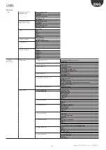
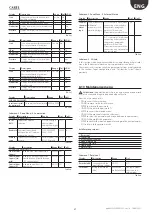
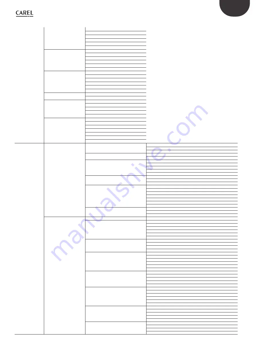
Menu tree

1. User

1. Alarm threshold 1/2

(Humidification)

Main probe threshold
High alarm
Low alarm
Limit probe thresholds
Alarm threshold
Alarm delay

1. Alarm threshold 1/2

(Evaporating cooling)

Main probe threshold

High alarm

Low alarm

Limit probe thresholds

Alarm threshold

Alarm delay

2. Clock

Hour

Day

Month

Year

Format

Day of the week

3. Enable scheduler

Scheduler on/off

Off and postpone sched.

4. Set scheduler

P1-1

P1-2

P2

P3

P4

5. Weekly scheduler

Monday

Tuesday

Wednesday

Thursday

Friday

Saturday

Sunday

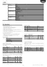
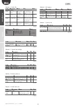
2. Installer 

(password 77)

1. Pump menu

1. Pump Setting 1/2 (i)

Operation mode: flow-rate control
High press.

Low press.

1. Pressurisation 2/2

Pressure threshold

Pump speed

2. Water supply 1/2

Low pressure probe

Alarm delay

Water treatment alarm logic

Water treatment warning logic

WTS relay logic

2. Water supply 2/2

TEST PRESS. INLET

Check time

Retries every:

3. Special pump functions 1/2 

FILLING

Enable valve delay

Duration

Automatic washing

Mode<only draining/ washing daily / periodic washing >

Hour of the day / time

Duration

3. Special pump functions 2/2

Enable valve delay

Valve delay

Min Ton step

2. Menu Zona 

1. Config. Inputs 1/10

Installation type 

1. Config. Inputs 2/10

HUMIDIFICATION

Operation type

Control Signal

Signal Type

Min Max

Offset

1. Config. Inputs 3/10

Limit signal

Signal Type

Min Max

Offset

1. Config. Inputs 4/10

EVAPORATIVE COOLING

Operation type

Control Signal

Signal Type

Min Max

Offset

1. Config. Inputs 5/10

Limit signal

Signal Type

Type (only if flow limit)

Min Max

Offset

1. Config. Inputs 6/10

Heat recovery activation

Min (*)

Max (*)

Offset (*)

Ist: On Off (*)

(*) only if heat recovery from ANALOGUE INPUT

1. Config. Inputs 7/10

Min (*)

Max (*)

Offset (*)

Ist:     On     Off (*)

(*) only if heat recovery from ANALOGUE INPUT

1. Config. Inputs 8/10

EVAPORATIVE COOLING

Control Temperature

P Factor

Integral time

Содержание optiMist EC005 0 Series

Страница 1: ...optiMist NO POWER SIGNAL CABLES TOGETHER READ CAREFULLY IN THE TEXT User manual evaporative cooling ...

Страница 2: ......

Страница 3: ...er unless specifically indicated in the user manual Do not drop hit or shake the humidifier as the inside parts and the linings may be irreparably damaged CAREL Industries adopts a policy of continual development Consequently CAREL reserves the right to make changes and improvements to any product described in this document without prior warning The technical specifications shown in the manual may...

Страница 4: ......

Страница 5: ...t system control 18 3 9 Cumulative alarm output J15 18 3 10 Alarm inputs from external devices 18 3 11 Frost protection alarm output 18 3 12 Backup cabinet signal 18 3 13 Supervisor network 19 3 14 Supervisory optiMist Table 19 4 PUMPING UNITS 22 4 1 Pumping unit with flow control configuration 22 5 DISTRIBUTION SYSTEM 23 5 1 Distribution and atomisation rack 23 5 2 Droplet separator 23 6 APPLICAT...

Страница 6: ......

Страница 7: ... section Since it is equipped with an inverter and pressure sensor it manages to control the flow of water produced at any moment thus ensuring maximum precision and minimum energy and water consumption distribution and atomisation system of pipes for transporting the pressurised water which contain the atomisation nozzles and drain valves droplet separator temperature and or humidity probes or co...

Страница 8: ...nnessioni elettriche lato scarico idraulico Fig 1 d Cabinet dimensions Heigh H 800 mmm 31 50 inch Width W 630 mmm 24 80 inch Depth D 300 mmm 11 82 inch Packaging dimensions Heigh H 1020 mmm 40 inch Width W 720 mmm 28 5 inch Depth D 410 mmm 16 inch Weight models EC005 53 kg 117 lb models EC010 53 kg 117 lb models EC020 55 kg 121 lb models EC040 55 kg 121 lb models EC080 59 kg 130 lb models EC100 59...

Страница 9: ...controller 5 Trasformer 6 Inverter 7 Fan Fig 1 e Components of the hydraulic section 11 10 4 5 6 1 3 7 12 16 13 14 15 2 8 9 Key 1 Motor 2 Pump 3 Temperature probe 4 Solenoid valve step 1 5 Monometer 6 Temperature valve 7 Solenoid valve step 2 8 Pressure probe 9 Cabinet drain valve 10 Filter case 11 Filter cartdige 12 Pressure reducer 13 Fill solenoid valve 14 Pressure switch 15 Manometer 16 Filter...

Страница 10: ...rial and remove the humidifier keeping it vertical at all times Store the packaging in a dry location cardboard boxes pallets bolts and fillers so that they may be reused humidity 20 80 RH non condensing temperature 1 40 C 1 8 Positioning the cabinet The humidifier should be positioned so as to guarantee the following open the front panel access to the inside parts for checks and maintenance conne...

Страница 11: ...yswingingittotheright inthedirection of the arrow Fig 1 i 1 11 Components and accessories Once having opened the packaging check the following are includedi opening key kit of screws with plugs for wall mounting inside the cabinet cable glands for the electrical connections tool for opening the water filter casing wall fit brackets ferrite see par 3 2 Fig 3 b user manual ...

Страница 12: ...AREL code ACKF000000 to remove solid particles from the supply water 3 flexible hose not supplied by CAREL 4 optiMist cabinet 5 hosescompletewithadapters 6 nozzles see Chap 4 7 manifolds 8 manifold connection hoses 9 drain valves Fig 2 a N B for direct connection to the mains water supply use pipes and fittings compliant with IEC 61770 Connections 1 2a 2b 3 Fig 2 b Key 1 water inlet G3 4 femmina 2...

Страница 13: ...nspection and maintenance are the nozzles and droplet separator In order to maintain system hygiene and to reduce system management costs Carel recommends supplying optiMist with water that has been demineralised by reverse osmosis as provided for in the principal norms such as UNI 8884 In particular Norm UNI 8884 Characteristics and treatment of water for cooling and humidification circuits sugge...

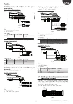
Страница 14: ...control probe B7 Evaporative cooling summer IEC limit probe Tab 3 a 3 4 Connections to the terminal board PEN GO Pump On Off remote enabling DEC GO Humidification control signals from external voltage free contact humidistat type ON OFF IEC GO Evaporative cooling control signals from external voltage free contact thermostat type ON OFF PR GO Humidification winter or evaporative cooling summer prio...

Страница 15: ...t evporative cooling enable REC G0 REC Fig 3 g Cabinet REC NO OFF NC ON GO COM Starting up damper Fig 3 h ON OFF and limit probe control CH CT For direct winter DEC humidification J9 J24 J2 J3 GR PEN GR PEN ROAL ROAL BKUP BKUP B B B B B B B out H T M G ROEN ROEN COM COM ONOF ONOF RKEN RKEN FLUX FLUX G0B G0B G0A G0A G0A G0A G0A G0A G0B G0B 1 2 Fig 3 i Key 1 humidistat ON OFF 2 humidity temperature ...

Страница 16: ...operation control and signal installer menu control type see chap 9 11 Installer Menu Note The use of shielded cables is recommended The cables must not be lodged near power cables at 230 V or near remote control switch wiring this way the risk of measurement error risks from electromagnetic interference can be avoided Modulating control with external controller contr P For humidification direct e...

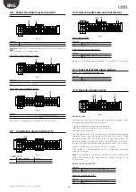
Страница 17: ...IEC fan damper modulating signal Modulating control with ambient humidity probe and temperature and humidity limit probe HH HT control 0 1 V 0 10 V 2 10 V 0 20 mA 4 20 mA For direct winter DEC humdification J9 J10 J12 J11 J13 J14 SERIAL CARD J9 J24 J2 J3 J4 J5 FIELD CARD p 1 2 T B B B B B B B Fig 3 r Key 1 humidity temperature limit probe 2 humidity probe CONNECTIONS optiMist cabinet Humidity prob...

Страница 18: ...AF Cabinet AF NO T 5 C OFF NC T 5 C ON AF COM 3 12 Backup cabinet signal HBT HBT BCKP G0 Fig 3 z Backup function The backup function allows the activation of a supporting cabinet in case of unexpected switch off of the main cabinet Two types of backup management are available HBT control on the heartbeat of the main control BMS control by supervisor The HBT control allows the activation of the bac...

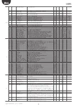
Страница 19: ...RO_Not_Ready Alarm Water Treatement System R 0 1 4 4 mAl_LP_Detected_New Alarm Low Pressure by pressostat ID5 R 0 1 5 5 Al_high_Temp_Bypass Alarm High temperature water in bypass R 0 1 6 6 Al_VFD_Not_Ready Alarm Inverter R 0 1 8 8 Al_Antifreeze_Temp Alarm low temperature in cabinet R 0 1 9 9 Al_HP_Detected Alarm drop separator clogged R 0 1 10 10 mAl_High_Press Allarme alta pressione da sonda R 0 ...

Страница 20: ... opened Dout 4 R 0 1 51 51 Dout_05 p 2 fill valve status 0 closed 1 opened Dout 5 R 0 1 52 52 Dout_06 Step 1 drain valve status 0 closed 1 opened Dout 6 R 0 1 53 53 Dout_09 Step 2 drain valve status 0 closed 1 opened Dout 9 R 0 1 54 54 Dout_03 Main line drain valve status 0 closed 1 opened Dout 3 R 0 1 55 55 Req_Wash Request of wash procedure running R 0 1 56 56 Dout_13 Anti freeze procedure activ...

Страница 21: ...eduler P2 OFF hour R W 0 23 0 hours 41 249 fascia2_min_off Scheduler P2 OFF minute R W 0 59 0 min 42 250 monday_type Monday scheduling 0 P1 1 P2 2 P3 always ON 3 P4 always OFF R W 0 3 0 43 251 tuesday_type Tuesday scheduling 0 P1 1 P2 2 P3 always ON 3 P4 always OFF R W 0 3 0 44 252 wednesday_type Wedneday scheduling 0 P1 1 P2 2 P3 always ON 3 P4 always OFF R W 0 3 0 45 253 thursday_type Thursday s...

Страница 22: ...tomise the water if the request increases the increase in flow rate will cause an increase in pressure that if it exceeds 15 bar will activate other atomising nozzles from the second modulation step with a subsequent decrease in the pressure bringing it within the optimum range Similarly if the humidification request decreases the flow rate and thus the pressure will decrease and if the latter app...

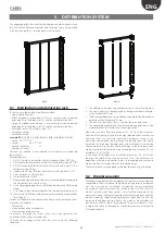
Страница 23: ... glass fibre or stainless steel filtering material They are available in 3 sizes in height and width of the modules the combination of which leads to 9 standard modules 5 DISTRIBUTION SYSTEM This paragraph briefly describes the distribution and atomisation systems for AHUs rack and droplet separator and for rooms These are described in detail in the optiMist distribution systems manual Fig 5 a Fig...

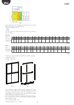
Страница 24: ...15 16 17 18 19 20 mm 527 679 831 1022 1174 1326 1478 1630 1820 1972 2124 2276 2428 2618 2770 2922 3074 3226 no separators 1 1 1 2 2 2 2 2 3 3 3 3 3 4 4 4 4 4 type separators no per mod 1x3 1x4 1x5 2x3 1x3 1x4 2x4 1x4 1x5 2x5 2x3 1x5 1x3 1x4 1x5 1x3 2x5 1x4 2x5 3x5 2x3 2x5 1x3 1x4 2x5 3x5 1x3 3x5 1x4 4x5 Tab 5 b There are 324 possible combinations identified by the following coding Example ECDS1007...

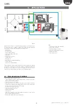
Страница 25: ...g it to saturation and is then used to cool the fresh outside air using an air air heat exchanger as shown in the following figure 6 1 Main advantages of optiMist The main advantages of optiMist are Highly reduced electrical consumption about 1 Watt for every litre hour of humidification capacity Maximum capacity 1000 kg h Loading solenoid valves for the distribution system inside the cabinet Exce...

Страница 26: ...ed on the value measured by the limit probe C control like the CH CT algorithm but without the limit probe The HH and TH algorithms are the most commonly used and recommended for optiMist installations The limit humidity probe described above is usually set to high values e g 80 rH so as to limit the maximum moisture in the air introduced into the duct and into the room This is especially recommen...

Страница 27: ...wise there is a risk that the probe could get wet thus constantly detecting humidity values close to the saturation point The humidity probe will further limit the maximum request TT CONTROL This type of control is used to modulate the capacity water flow rate with a temperature control probe and a temperature limit probe The control probe is usually installed in the centre of the room and the lim...

Страница 28: ...onfigure the outlet humidity control and the indirect evaporative cooling contribution control at the same time ATTENTION the operation of the two zones is mutually exclusive the two zones therefore will never work at the same time Selecting the active zone will depend upon a the priority assigned by digital input ID4 closed contact for I E C open contact for Humidification see section 3 x b the c...

Страница 29: ...ions Once this procedure is correctly completed the machine will be ready to operate Access to the Wizard section will then be possible through the Installer Menu Wizard or when the machine is restarted if the option Show Wizard at start up has not been disabled 8 5 Keypad 6 4 5 3 2 1 Fig 8 a button function 1 alarm list active alarms and reset any alarms present 2 PRG return to the main screen fr...

Страница 30: ...gh pressure kg h lb h Prod max red IEC Maximum production due to reduction for high pressure kg h lb h Tab 8 e Whenever the optiMist humidifier is configured to control the section dedicated to Evaporative Cooling IEC and the heat recovery activation is giving by an analog signal the value of that signal will be shown in screen Info 3 3 8 8 SET screen This is used to set the main values for the hu...

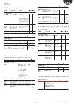
Страница 31: ...t warning logic WTS relay logic 2 Water supply 2 2 TEST PRESS INLET Check time Retries every 3 Special pump functions 1 2 FILLING Enable valve delay Duration Automatic washing Mode only draining washing daily periodic washing Hour of the day time Duration 3 Special pump functions 2 2 Enable valve delay Valve delay Min Ton step 2 Menu Zona 1 Config Inputs 1 10 Installation type 1 Config Inputs 2 10...

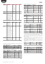
Страница 32: ...password 4 Supervision 1 2 Id for BMS Baud rate Protocol type 4 Supervision 1 2 On off by supervisor Reg by superv Hum Reg by superv IEC 5 External Alarms Drop separator alarm logic 3 Wizard 1 10 Type optiMist Model Unit of measure 3 Wizard 2 10 Installation type 3 Wizard 3 10 Number branches Nominal flow rate Nominal flow rate IEC 3 Wizard 4 10 HUMIDIFICATION Operation type Control Signal Signal ...

Страница 33: ...ain probe threshold Alarm high High humidity alarm threshold 0 100 rH 100 rH rH Alarm low Low humidity alarm threshold 0 100 rH 0 rH rH Limit probe thresh Alarm high High humidity temperature limit alarm threshold 0 150 C F o 0 100 rH 100 rH C o F o rH Alarm delay Alarm signalling delay 0 99 1 min Tab 8 i Where there is a zone dedicated to evaporative cooling the following screen will also appear ...

Страница 34: ...ntains the menus with the installer parameters corresponding to the pumping station Display Description Range Def UoM PUMP SETTINGS Mode Flow rate control optiMist operating mode High press Maximum modulation limit activation threshold for the next modulation step 4 15 bar 58 218 psi 15 bar 218 psi bar psi Low press Minimum modulation limit deactivation limit for the modulation step 4 15 bar 58 21...

Страница 35: ...um control signal value 0 to 100 20 C to 70 C 100 70 C C F Offset Probe reading correction offset 0 to 100 20 C to 70 C 0 C F Tab 8 w Display Description Range Def UoM Config Inputs 5 8 EVAPORATIVE COOLING Limit Type of limit signal B7 analog inlet NTC 0 135oh 0 1V 0 10V 4 20mA 0 20mA Type limit signal correspondence only if flow signal Air lock or Fan Air lock Min Minimum control signal value 0 1...

Страница 36: ...C N O Flow switch logic Flow switch digital input logic N O N C N C Language User language choice English Italiano Deutsche Espanol Français English Show language choice at start up Show language choice in the first start up screen YES to NO YES Tab 8 ae Display Description Range Def UoM SPECIAL FUNCTIONS 2 3 optiMist as backup Select enabling of this cabinet as a backup cabinet NO ID8 life sign c...

Страница 37: ...from Superv Hu mid Enable control from supervision Humidification if Humidification IEC configuration NO YES NO Control from Superv IEC Enabled control from IEC supervision NO YES NO Tab 8 ao Submenu 2 Zone Menu 5 External Alarms Display Description Range Def UoM External Alarms Droplet separator alarm logic Droplet separator differential pressure switch alarm input logic N O normally open when co...

Страница 38: ...read by humidification main input B1 Humid Limit View signal read by humidification limit input B2 AUX View signal read by auxiliary temperature input B5 Tab 8 au Display Description Range Def UoM INSTANTANEOUS READINGS 2 2 Main IEC View signal read by IEC main input B6 IEC Limit View signal read by IEC limit input B7 Tab 8 av Submenu 4 Manual procedure Display Description Range Def UoM Manual pro...

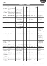
Страница 39: ...he defrost Droplet separator clogged alarm droplet separator clogged check the status of the droplet separator s manual active Stop production on signalgivenbya differentialpressureswitch thatseesanupstream downstreampressure differenceforthedroplet separator Whenthere are2dropletseparators Humidification IEC 2 pressureswitcheswillbe connectedinseries P selectable delayselectable High pressure war...

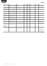
Страница 40: ... value measured by the main probe is greater than the humidity alarm threshold check the parameter setting manual not active signal only on Low temperature main probe IEC alarm value measured by the main probe is less than the humidity alarm threshold check the parameter setting manual not active signal only on High humidity temperature limit alarm IEC value measured by the limit probe is greater ...

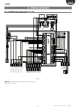
Страница 41: ...ree Filter Tabella Fusibili Fuses Table F1 F2 12A F 10 3x38 600V F3 F4 4A F 5x20 600V F6 2 5A T 5x20 250V E E E E F A A B A A A A A A B A D D D C Sonda umidità T principale inverno 1 0 10V_4 20mA NTC Sonda umidità T limite inverno 1 0 10V_4 20mA NTC Sonda umidità T principale estate 1 0 10V_4 20mA NTC Sonda umidità T limite estate 1 0 10V_4 20mA NTC ON OFF WINTER ON OFF SUMMER ESTATE INVERNO Uscit...

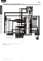
Страница 42: ...se Free Filter Tabella Fusibili Fuses Table F1 F2 12A F 10 3x38 600V F3 F4 4A F 5x20 600V F6 2 5A T 5x20 250V E E E E F A A B A A A A A A B A D D D C Sonda umidità T principale inverno 1 0 10V_4 20mA NTC Sonda umidità T limite inverno 1 0 10V_4 20mA NTC Sonda umidità T principale estate 1 0 10V_4 20mA NTC Sonda umidità T limite estate 1 0 10V_4 20mA NTC ON OFF WINTER ON OFF SUMMER ESTATE INVERNO U...

Страница 43: ... 4 f Connect the connection pipe s between the cabinet G1 2 f and the distribution system G1 2 f of the pressurized water outlet of the pump towards the lower orifice connect the control signals and check that the control settings are compatible Connect the discharge solenoid valve to the related clamps Connect the electric supply cable to the appropriate clamps L N PE Open the manual water valve ...

Страница 44: ...010 0 ECKM373F50 motor kit 0 37 kW 3 4 poles 230 V 50 Hz CE for EC020 040 0 ECKM753F50 motor kit 0 75 kW 3 4 poles 230 V 50 Hz CE for EC080 100 0 ECKM253F60 motor kit 0 25 kW 3 4 poles 230 V 60 Hz UL for EC005 010 U ECKM373F60 motor kit 0 37 kW 3 4 poles 230 V 60 Hz UL for EC020 040 U ECKM753F60 motor kit 0 75 kW 3 4 poles 230 V 60 Hz UL for EC080 100 U ECKVFD0250 EC005 010 inverter 0 25 kW 230 V ...

Страница 45: ......
Страница 46: ...CAREL INDUSTRIES HQs Via dell Industria 11 35020 Brugine Padova Italy Tel 39 049 9716611 Fax 39 049 9716600 e mail carel carel com www carel com Agenzia Agency optiMist 0300065EN rel 1 6 18 06 2021 ...

Отзывы: