S
ERVICE
P
ROCEDURES
61
F
IGURE
21:
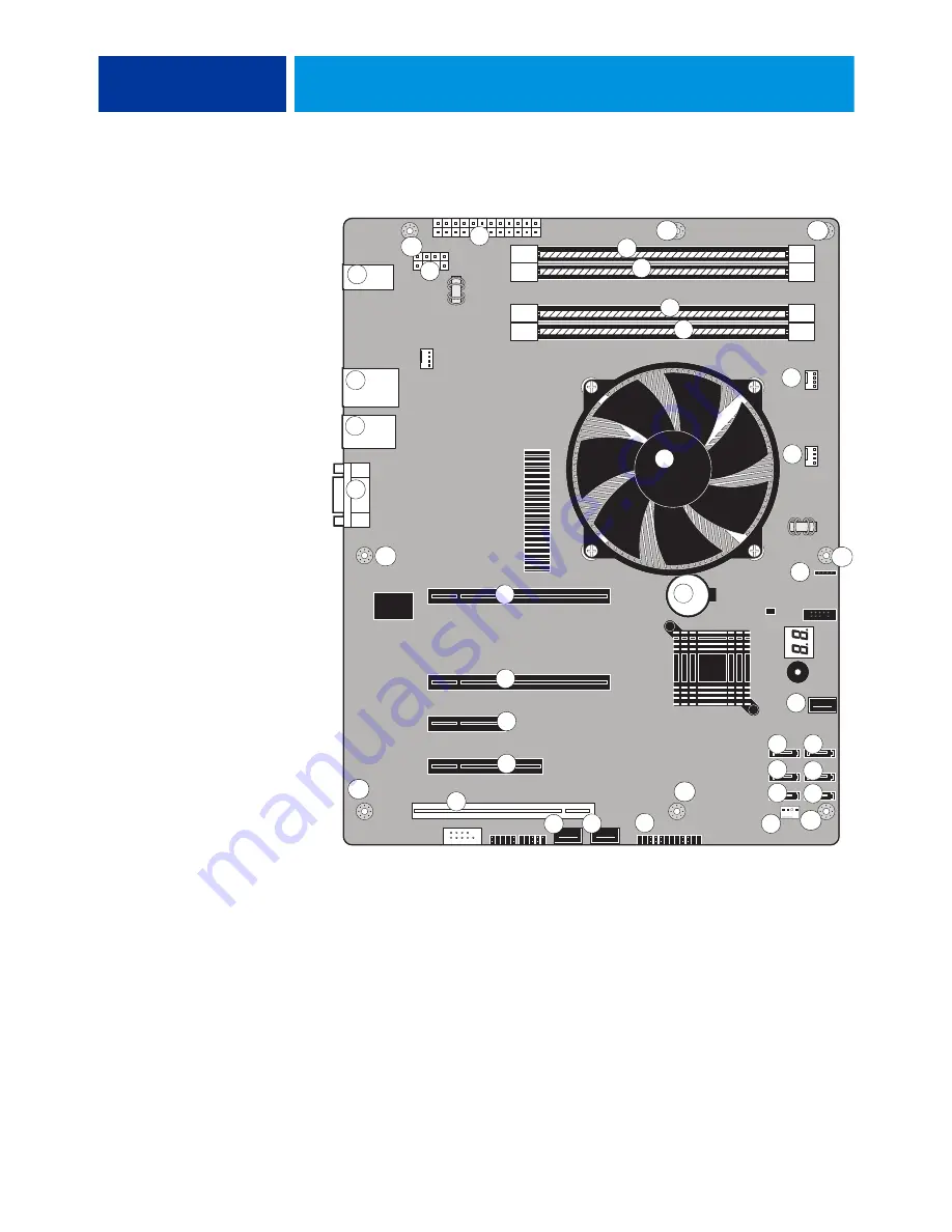
Diagram of the ColorPASS motherboard
Key
1. USB ports (x4)
2. Network interface/USB ports (x2)
3. Command/Status port
4. Monitor
5. CPU power (PW1)
6. Motherboard power (PW2)
7. CPU, heatsink, CPU fan
8. Battery (BT1)
9. Copier interface board (PCI-E6)
10. Empty PCI-E (J12)
11. Empty PCI-E (J11)
12. Empty PCI-E (J10)
13. Empty PCI-X (J9)
14. DIMM 4
15. DIMM 3
16. DIMM 2
17. DIMM 1
18. CPU fan power (FAN 1)
19. Not used
20. Speaker (J40)
21. UIB cable (USB3)
22. SATA 3 (Not used)
23. SATA 0: DVD drive data connection
24. SATA 4 (Not used)
25. SATA 1: Hard disk drive data connection
26. SATA 5 (Not used)
27. SATA 2 (Not used)
28. Front panel USB port cable (USB2)
29. Front panel USB port cable (USB4)
30. PWR & RST (JP4)
31. Front panel fan (FAN 4)
MH—Mounting holes
16
MH
MH
MH
MH
MH
MH
11
MH
MH
1
2
3
4
5
6
7
8
9
10
12
13
14
15
17
18
19
20
22
21
23
24
25
26
27
28
29
30
31
Содержание ColorPASS-GX400
Страница 144: ......


