background image

S

ERVICE

 P

ROCEDURES

49

T

O


SHUT


DOWN


FROM


THE

 C

OLOR

PASS C

ONTROL

 P

ANEL

N

OTE

:

Notify the network administrator before you remove the ColorPASS from 

the network.

1 Make sure that the ColorPASS is not receiving, processing, or printing any jobs.

If Printing appears on the copier touch panel, the ColorPASS is processing. You must wait 
until the system finishes and reaches Idle before restarting or shutting down.

If the system has just finished processing, wait at least five seconds after the system reaches 
Idle before beginning the shutdown procedure.

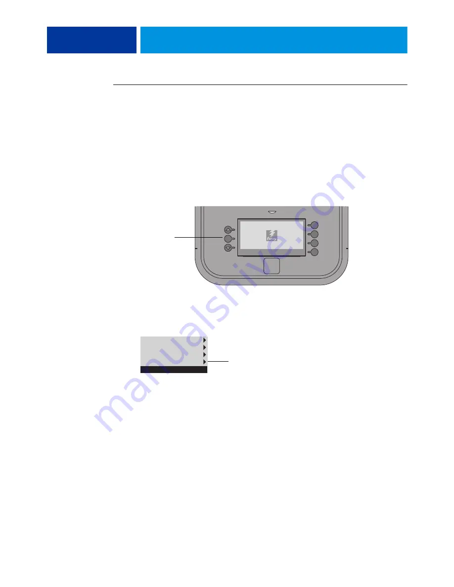
2 If the logo screen is displayed, press the Menu button once to display the Functions menu.

3 Select Shut Down System.

N

OTE

:

Use the reset button on the front of the ColorPASS only if the system is unresponsive 

to keyboard or mouse actions.

Allow the system to shut down and power off. 

Before accessing internal components following a shutdown, make sure that all cables are 
disconnected from the back of the ColorPASS.

This logo screen indicates that the ColorPASS is Idle.

Server name

Menu button

Eject CD/DVD
IP Address
Restart Server
Shut Down System

Server name


Immediately shuts down 
the ColorPASS

Содержание ColorPASS-GX400

Страница 1: ...Canon ColorPASS GX400 Installation and Service Guide A guide for service technicians 45111271 3 August 2012 ...

Страница 2: ...ocumentation is subject to change without notice and does not represent a commitment on the part of EFI The documentation is further covered by Legal Notices distributed with this product The documentation may be provided in conjunction with EFI Software Software and any other EFI product described in the documentation The Software is furnished under license and may only be used or copied in accor...

Страница 3: ...e 12 Terminology and conventions 12 Precautions 14 Creating an ESD safe environment 15 Tools you will need 18 INTRODUCTION 19 Features 19 How the ColorPASS operates 20 INSTALLATION 22 Installation sequence 22 Checking the customer site 24 Copier readiness 24 Setting customer expectations 25 Unpacking the ColorPASS 26 Connecting the ColorPASS 28 Completing installation and starting up 31 CONTENTS ...

Страница 4: ...shutting down restarting and rebooting 41 SERVICE PROCEDURES 43 Overview 43 ColorPASS overview diagrams 44 Accessing internal components 48 Shutting down the system 48 Opening the ColorPASS 51 Removing and replacing boards 55 Copier interface board 55 User interface board assembly 57 Motherboard 60 Removing the motherboard 60 Replacing the motherboard 64 Verifying new motherboard installation and ...

Страница 5: ... up the system configuration 106 Restoring the system configuration 107 Installing system software 107 System software installation error messages 109 Installing software patches 110 System updates 110 TROUBLESHOOTING 111 Troubleshooting process 111 Preliminary on site checkout 112 Checking external connections 113 Checking internal components 114 Inspecting the system 115 Normal startup sequence ...

Страница 6: ...FICATIONS 132 Hardware features 132 Physical specifications 132 Networking and connectivity 133 User software 133 Safety and emissions compliance 133 SERVICING THE COLORPASS WITH FURNITURE 134 Procedures 134 INDEX 145 ...

Страница 7: ...panel 36 FIGURE 10 Front and back panels 44 FIGURE 11 Back panel and internal side view 45 FIGURE 12 Exploded view of ColorPASS components 46 FIGURE 13 Power and data cable connections in the ColorPASS 48 FIGURE 14 Removing replacing the side panels 52 FIGURE 15 Removing replacing the front panel 53 FIGURE 16 Removing replacing the top panel 54 FIGURE 17 Diagram of the copier interface 55 FIGURE 1...

Страница 8: ...moving replacing the hard disk drive bracket 92 FIGURE 33 Removing replacing the hard disk drive from in the hard disk drive bracket 93 FIGURE 34 component sled with switch bank assembly 96 FIGURE 35 Removing replacing the component sled from the chassis 97 FIGURE 36 Removing replacing the switch bank assembly 98 FIGURE 37 ColorPASS DVD drive 100 FIGURE 38 Removing replacing the DVD drive 101 FIGU...

Страница 9: ... by non authorized personnel NOTE The term ColorPASS is used throughout this guide to refer to the Canon ColorPASS GX400 The term copier is used to refer to the Canon imageRUNNER ADVANCE C9200 C7200 series and Canon imageRUNNER ADVANCE C5255 ColorPASS customer media pack The ColorPASS customer media pack contains the following System Software media User Software media user documentation Drivers an...

Страница 10: ... this guide see the sections beginning on page 11 Customer documentation Customer documentation also known as user documentation is designed primarily for users and administrators It also contains information that may be useful to service technicians therefore cross references to the customer documentation are included in the Installation and Service Guide Service technicians can obtain user docum...

Страница 11: ...and replacement procedures for ColorPASS components restoring and verifying functionality System and user software Overview of the system software installing system and user software Troubleshooting Common problems and ways of correcting them startup error messages general system error conditions Specifications ColorPASS specifications Servicing the ColorPASS with furniture FACI option Assembly an...

Страница 12: ... sure that the customer site has an appropriate electrical outlet and sufficient physical space for the ColorPASS Unpacking the ColorPASS Installing and connecting the ColorPASS Servicing the ColorPASS components Installing system and user software on the ColorPASS Network administrator In this guide responsibilities attributed to the network administrator include the following Verifying that the ...

Страница 13: ...VD 3 Microsoft Windows 7 Professional for Embedded Systems x64 operating system software Backup Recovery and Upgrade DVD 4 User Software For other terms used to identify components of the ColorPASS see the reference key in Figure 12 on page 46 Connectors and components labeled not used Connectors and components labeled not used are disabled or are not used in the standard ColorPASS configuration D...

Страница 14: ...nca el servidor de impresión agarrándolo por el panel superior El panel superior no soporta el peso del sistema ADVERTÊNCIA Nunca erga o servidor de impressão pelo painel superior O painel superior não suporta o peso do sistema WAARSCHUWING Til de afdrukserver nooit op door het bovenpaneel vast te nemen Het bovenpaneel kan het gewicht van het systeem niet dragen When connecting or disconnecting th...

Страница 15: ...between the customer s computer existing laser printers and other prepress equipment Never disturb the LAN by breaking or making a network connection altering termination installing or removing networking hardware or software or shutting down networked devices without the knowledge and explicit permission of the system or network administrator or the shop supervisor Unless you are the network admi...

Страница 16: ...s by their opposing edges only and avoid touching the contacts on the edge of the board Power Supply Cord Notice The power supply cord is used as the main disconnect device Ensure that the socket outlet is located installed near the equipment and is easily accessible ATTENTION Le cordon d alimentation doit être débranché pour une mise hors tension totale du produit La prise de courant doit être si...

Страница 17: ...o paikallisten määräysten mukaisesti ADVARSEL Eksplosjonsfare ved feilaktig skifte av batteri Benytt samme batteritype eller en tilsvarende type anbefalt av apparatfabrikanten Brukte batterier kasseres i henhold til lokal lovgivning VARNING Risk för explosion om batteriet byts ut mot en felaktig batterityp Byt bara ut batteriet mot en batterityp som har godkänts av tillverkaren Hantera använda bat...

Страница 18: ...nden Leitern verwendet wird DVERTENCIA Este producto depende de la instalación del edificio en lo relativo a la protección frente a cortocircuitos sobretensión Asegúrese de utilizar un fusible o un interruptor de circuito que no sea de más de 120 V CA 15A en EE UU 240 V CA 10A internacional en los conductores de fase todos los conductores que transportan corriente ADVERTÊNCIA Esse produto depende ...

Страница 19: ...ters Print color grayscale and black and white jobs Use the copier as a high resolution color scanner with Fiery Scan software Use 136 resident fonts 126 Adobe Type 1 PostScript and 10 TrueType plus two Adobe Multiple Master fonts used for font substitution when printing PDF files Command WorkStation or any third party LaserWriter downloader such as the Adobe Font Downloader can be used to downloa...

Страница 20: ...herboard includes an Intel Core i5 660 3 3GHz CPU that controls the image data transfer to and from the motherboard and runs the interpreter The interpreter rasterizes the page description file and compresses the image pattern into memory using compression technology High speed DIMMs dual in line memory modules on the motherboard hold the image data during printing The ColorPASS is configured with...

Страница 21: ...network interface 1000BaseT controller Lower RJ 45 Command Status ENET Crossover User interface board PCI E Keyboard and mouse option Monitor option PCI X 133 100 SATA 0 USB devices Dongles ColorPASS DIMM 4 PCI North bridge memory controller Copier interface board PCI E DIMM 3 DIMM 2 DIMM 1 Reset PCI X not used PCI E x 16 slots x4 signal not used DVD drive HDD SATA 2 SATA 4 SATA 1 SATA 3 SATA 5 PC...

Страница 22: ...apter is designed to make your job as easy as possible Installation problems are easier to avoid and diagnose if you proceed from the component to the system level and verify functionality at each stage Figure 3 on page 23 outlines the recommended installation procedure for connecting the ColorPASS to the copier Because the ColorPASS is a node on the customer s computer network make sure that you ...

Страница 23: ...te SeeQuence Impose and SeeQuence Compose features in the same workflow About SeeQuence Suite kits Fiery SeeQuence Suite is available in the following optional kit configurations Fiery SeeQuence Impose kit includes the Adobe Acrobat Enfocus PitStop DVD and a SeeQuence Impose dongle Fiery SeeQuence Compose kit includes the Adobe Acrobat Enfocus PitStop DVD and a SeeQuence Compose dongle Fiery SeeQu...

Страница 24: ...tments Print the copier Test Page before you install the ColorPASS If the image indicates that the copier needs adjustment inform the customer After getting approval complete the necessary copier service Power Is a dedicated grounded electrical outlet for the ColorPASS available near the copier Locate the grounded electrical outlet that will supply power to the ColorPASS Do not run the ColorPASS a...

Страница 25: ...etwork administrator installs a network connector for the ColorPASS and confirms network functionality with the connector in place before the date scheduled for the ColorPASS installation The network administrator must make a networked computer available during the installation The appropriate software must be installed in advance Documentation for the networked computer and network operating soft...

Страница 26: ...eso del sistema AVISO Nunca erga o servidor de impressão pelo painel superior O painel superior não suporta o peso do sistema WAARSCHUWING Til de afdrukserver nooit op door het bovenpaneel vast te nemen Het bovenpaneel kan het gewicht van het systeem niet dragen TO UNPACK THE COLORPASS 1 Open the box and remove the packing material Save the original boxes and packing material in case you need to t...

Страница 27: ...e Suite software comprises integrated job preparation tools that allow you to do the following SeeQuence Impose applies imposition layouts to jobs for custom printing binding and trimming It also applies impositions to variable data jobs and saves imposed jobs as PDF files SeeQuence Compose allows you to define the chapter divisions of a job print ranges of pages on varying types of media insert b...

Страница 28: ...information about the monitor keyboard and mouse see the documentation that accompanies the optional kit Follow standard ESD precautions when handling components FIGURE 5 ColorPASS connections Front panel Back panel USB ports Power button Control panel DVD drive Power connector USB ports x2 Network port RJ 45 Command Status port RJ 45 USB ports x4 DVI port Copier interface port Reset button NOTE U...

Страница 29: ...e screws completely on both ends of the cable 4 Connect the scan crossover cable to the scan ports on the ColorPASS and the copier NOTE The straight through network cable at the customer site and the scan crossover cable included with the ColorPASS look similar but are not interchangeable Make sure that you connect the scan crossover cable to the lower RJ 45 port on the ColorPASS back panel see Fi...

Страница 30: ... 5 or higher 4 pair 8 wire short length 1000BaseT Category 5e or higher 4 pair 8 wire short length After power on the network administrator should perform Network Setup verify the network connection verify that the ColorPASS appears in the list of printers and then print a few test documents from a networked computer that will use the ColorPASS For more information see Configuration and Setup whic...

Страница 31: ...r 4 Perform any required system software upgrades For instructions see the documentation that accompanies the ColorPASS service upgrade Updates to Fiery Server Software may be available for the ColorPASS from a variety of sources for example System Updates see page 110 patches provided on CD or patches downloaded by the customer Windows operating system updates should be obtained from Microsoft di...

Страница 32: ... page 35 NOTE A third user interface the Fiery Advanced Controller Interface FACI which includes a monitor keyboard and mouse is sold separately as an optional kit Using the ColorPASS Control Panel The Control Panel on the front of the ColorPASS allows you to do the following Eject CDs and DVDs On some systems a hardware eject button is also provided below the disc slot Shut down restart or reboot...

Страница 33: ...Server Shut Down System and Reboot System options Flashing amber The ColorPASS is starting up and the BIOS has established communication with the User Interface Board UIB Flashing green The ColorPASS is continuing startup and the Windows operating system has established communication with the UIB Solid green The ColorPASS is powered on and in the Idle state Solid amber The ColorPASS is powered off...

Страница 34: ...olorPASS is temporarily interrupted and all currently processing jobs are aborted and may be lost Shut Down System shuts down all ColorPASS server software and powers off the system Always select this option to power off the system Reboot System hard reset shuts down all ColorPASS activity properly and then reboots NOTE Avoid using the reset button on the front panel as doing so may cause the syst...

Страница 35: ...To access the ColorPASS areas of the interface scroll as follows Main Menu Printer screen Info screen Functions menu also see page 36 FIGURE 8 Accessing the ColorPASS areas of the copier touch panel Main Menu Press Printer to advance to the Printer screen Press the Printer Status Settings button to display the Info screen Press the Functions button to display the Functions menu Info screen Display...

Страница 36: ...print jobs of other users The functions available from the Functions menu are described on page 37 Many of these functions are also available from Command WorkStation FIGURE 9 Using the ColorPASS Functions menu from the copier touch panel Use the selection buttons on the right to select an option Use the up and down buttons to scroll through the list of functions Press the Done button to return to...

Страница 37: ...e Configuration page also provides version information for the BIOS chip and information about any installed options or special features included in the ColorPASS Printing the Configuration page can also be helpful during installation Setup and service After installing the ColorPASS including connecting to the network and before default settings are changed in Run Setup you can obtain a record of ...

Страница 38: ...m the job management tools Clear Server also clears the Job Log all jobs archived on the ColorPASS hard disk drive the index of archived jobs all FreeForm masters and the index of FreeForm masters To preserve the Job Log print or export the Job Log before you choose Clear Server To clear the ColorPASS access the Functions menu and choose Clear Server You are asked to confirm your selection You are...

Страница 39: ...h updates are available directly from Microsoft EFI does not maintain or provide them via the System Updates feature Print pages menu This section describes how to print the Test Page and Configuration page from the Print Pages menu described on page 37 To navigate to the Print Pages menu from the copier touch panel scroll as follows Main Menu Printer screen Info screen Functions menu Print Pages ...

Страница 40: ...sends the selected page s to the copier Network Status LEDs Two LEDs next to the Ethernet connector indicate the network speed When a data transfer occurs between the ColorPASS and the network the appropriate LED s blink to indicate network activity For additional network information see Configuration and Setup which is part of the user documentation set NOTE The Ethernet network cable at the cust...

Страница 41: ...S by pressing the power button on the front panel The power supply automatically senses the correct voltage Allow startup to proceed without interruption Do not press any buttons on the Control Panel while the system is starting TO SHUT DOWN RESTART OR REBOOT FROM THE COLORPASS CONTROL PANEL 1 Make sure that the Info screen on the copier touch panel displays Idle see page 35 If Printing or Process...

Страница 42: ...ystem has just finished processing wait at least five seconds after the system reaches Idle before beginning the shutdown procedure NOTE Notify the network administrator before you remove the ColorPASS from the network 3 Press the Functions button to display the Functions menu 4 Press the Shut Down button 5 Select Restart Server Shut Down System or Reboot System Before accessing internal component...

Страница 43: ... DIMMs CPU CMOS jumpers and battery Fans Power supply Hard disk drive HDD Replacement parts are available from your authorized service representative The terms replace and replacing are used throughout this document to refer to the reinstallation of existing components Install new components only when necessary If you determine that a component that you have removed is not faulty reinstall it When...

Страница 44: ...GURE 10 Front and back panels Front panel Back panel USB ports Power button Control panel DVD drive Power connector Network port USB ports x4 USB ports x2 Copier interface port Reset button NOTE Use the reset button only if the system is unresponsive to keyboard or Eject button Power switch Command Status port DVI port ...

Страница 45: ...USB ports x2 5 Command Status port 6 DVI port 7 Copier interface board PCI E6 8 CPU cooling assembly 9 Power supply 10 DIMM slots 11 DVD drive 12 Removable drive option 13 Hard disk drive in bracket 14 Motherboard 15 Front fan NOTE Cables UIB and front panel USB ports are not shown 1 14 15 13 12 11 10 2 3 4 5 6 7 8 9 7 6 ...

Страница 46: ... DVD drive 7 Front panel 8 Upper faceplate 9 UIB cable 10 Hard disk drive bracket 11 Hard disk drive 12 Side panel left 13 Hard disk drive data cables 14 DVD drive power data combination cable 15 CPU cooling assembly 16 Copier interface board 17 DIMMs 18 CPU 19 Battery 20 Motherboard 21 Fan 22 Chassis 23 Power supply 24 Side panel right NOTE UIB buttons CPU fan cable tie wraps cable clamps dongle ...

Страница 47: ...d Hard disk drive power connector 2 Front panel USB port cables Front panel Motherboard connectors J22 J35 see detail above 3 UIB cable User interface board Motherboard connector USB 3 see detail above 4 Power and reset cables Front panel Motherboard connector JP4 see detail above 1b 1c 9 5 NOTE Power supply DIMMs and copier interface are not shown 1a 8 4 7 6 1d 3 2 2 3 4 5 6 7 8 ...

Страница 48: ...ASS off the network If you are cycling power wait at least 10 seconds before powering back on If you are unable to shut down the ColorPASS through the Control Panel or the copier touch panel power off by holding down the power button on the front of the ColorPASS for up to eight seconds Using the reset button may cause the system to operate unpredictably Use the reset button on the front of the Co...

Страница 49: ...nds after the system reaches Idle before beginning the shutdown procedure 2 If the logo screen is displayed press the Menu button once to display the Functions menu 3 Select Shut Down System NOTE Use the reset button on the front of the ColorPASS only if the system is unresponsive to keyboard or mouse actions Allow the system to shut down and power off Before accessing internal components followin...

Страница 50: ...ng or shutting down If the system has just finished processing wait at least five seconds after the system reaches Idle before beginning the shutdown procedure 2 On the copier touch panel tap Printer and then tap Printer Server Status Settings NOTE If Printer does not display tap Show All 3 Tap Functions 4 Tap the down arrow to scroll to Shut Down 5 From the Shut Down screen choose Shut Down Syste...

Страница 51: ...so do sistema WAARSCHUWING Til de afdrukserver nooit op door het bovenpaneel vast te nemen Het bovenpaneel kan het gewicht van het systeem niet dragen TO OPEN THE COLORPASS 1 Shut down the ColorPASS see page 48 2 Remove all cables from the back of the ColorPASS 3 If the ColorPASS is mounted on the optional furniture and the optional monitor is attached perform the disassembly instructions in Servi...

Страница 52: ...the panel off the chassis FIGURE 14 Removing replacing the side panels 3 To replace the panel fit the front edge of the panel on the pivot post in the chassis 4 Rotate the panel closed against the back of the chassis and replace the screws that you removed earlier Make sure not to damage cables as you replace the panel Fold all cables inside the chassis before closing the panel against the chassis...

Страница 53: ...ecure the front panel to the chassis and then lift the panel off of the chassis First remove the two top tabs then the two middle tabs and then the two bottom tabs FIGURE 15 Removing replacing the front panel 3 To replace the front panel align the four cutouts in the panel with the power and reset buttons and front USB ports 4 Press the panel against the chassis to snap it into place Snap the tabs...

Страница 54: ...l Slide the top panel a few inches toward the front of the chassis to disengage the hooks in the panel from the slots in the top of the chassis NOTE You may need to tap the back edge of the panel toward the front of the chassis to disengage the panel 3 Detach the UIB cable from the motherboard 4 Remove the panel from the chassis Carefully route the UIB cable out of the hole in the top of the chass...

Страница 55: ... the locking bolt through the cutout in the left side of the top panel Removing and replacing boards This section includes procedures for removing and replacing the following boards Copier interface User interface board Motherboard The ColorPASS is shipped from the factory with a standard board configuration as shown in Figure 11 on page 45 If optional components have been installed see the docume...

Страница 56: ...board connector PCI E6 Grasp the copier interface board at the front and back edges and gently pull the board straight out of its motherboard connector 5 Place the copier interface board in an antistatic bag TO REPLACE THE COPIER INTERFACE BOARD 1 Seat the copier interface board in connector PCI E6 on the motherboard the topmost connector and then secure it to the chassis with the board mounting b...

Страница 57: ... window LCD Four line selection buttons Up and Down buttons Menu button Jewel lights The UIB cable is routed from a connector on the back of the user interface board to connector USB3 on the motherboard see Figure 21 on page 61 FIGURE 18 Diagram of the user interface board front and back Back Front Line selection button pads UIB cable connector USB3 Activity lights LEDs Display window Up button pa...

Страница 58: ...om the connector on the back of the UIB Detach the UIB cable by grasping the cable connector Avoid pulling on the cable 4 Remove the four screws that secure the UIB to the underside of the top panel 5 Remove the UIB from the top panel Be sure to remove the plastic lens that covers the display window of the UIB FIGURE 19 Removing replacing the user interface board 6 If you are removing the UIB to r...

Страница 59: ...w of the UIB 5 Secure the UIB to the underside of the top panel Grasp the UIB in one hand while using the other hand to hold the plastic lens steady against the UIB display window Place the UIB in the mounting area of the top panel and carefully fit the buttons through the cutouts in the top panel as you hold the plastic lens in place Replace the four screws that secure the UIB to the underside of...

Страница 60: ...rboard attaches to the side of the chassis below the power supply Before you remove the motherboard you must remove the following The left panel All boards installed on the motherboard All cables connected to the motherboard including the motherboard power cable CPU power cable front panel fan cable hard disk drive data cable DVD drive power and data combination cable power button cable reset butt...

Страница 61: ...10 13 Empty PCI X J9 14 DIMM 4 15 DIMM 3 16 DIMM 2 17 DIMM 1 18 CPU fan power FAN 1 19 Not used 20 Speaker J40 21 UIB cable USB3 22 SATA 3 Not used 23 SATA 0 DVD drive data connection 24 SATA 4 Not used 25 SATA 1 Hard disk drive data connection 26 SATA 5 Not used 27 SATA 2 Not used 28 Front panel USB port cable USB2 29 Front panel USB port cable USB4 30 PWR RST JP4 31 Front panel fan FAN 4 MH Moun...

Страница 62: ...st remove any plastic cable clamp s securing internal cables and reusable tie wraps if present Front panel fan cable FAN 4 Reset button cable JP4 Power button cable JP4 Speaker cable JP5 UIB cable USB3 Front panel USB port cables USB2 and USB4 DVD drive cables SATA data cable from motherboard connector SATA 0 Power and data combination cable from the back of the DVD drive Hard disk drive cables SA...

Страница 63: ...g the motherboard to the chassis for screw locations see Figure 21 on page 61 3 Remove the motherboard from the chassis Lift the edge of the motherboard see Figure 22 Make sure that the back panel connectors on the motherboard clear the chassis while you lift it out of the chassis Do not touch the contacts and avoid using excessive force During service avoid using excessive force and always place ...

Страница 64: ... in the order listed If troubleshooting strategies checking cables and connections reinstalling system software and so forth do not solve the problem and you suspect that the hard disk drive or the motherboard is faulty always troubleshoot in the following order Troubleshooting in the wrong order will cause the system to malfunction In general it is highly unlikely that both the hard disk drive an...

Страница 65: ... you are troubleshooting The ColorPASS can remain in Service Mode indefinitely Use Service Mode to carefully verify the new motherboard before transferring options to the new motherboard Transferring options to the new motherboard permanently customizes the new motherboard Once customized the motherboard cannot be returned to inventory or installed in another ColorPASS If the new motherboard does ...

Страница 66: ...e old motherboard onto the new motherboard Doing so can damage the ColorPASS BIOS chips are not interchangeable 2 Install the motherboard in the chassis Angle the motherboard so that the back panel connectors on the motherboard fit into the cutouts in the back of the chassis see Figure 22 on page 63 Make sure that the flexible grounding tabs on the cutouts for the network ports make contact with t...

Страница 67: ...nnector SATA 0 NOTE Connect the thin black SATA power cable connectors to the hard disk drive and DVD drive Do not connect the white 4 pin power cable connectors Connecting both types of power cables will damage the hard disk drive and DVD drive Front panel USB port cables USB2 and USB4 see detail Speaker cable JP5 see detail Make sure that the small triangle on the cable connector is aligned with...

Страница 68: ...nctionality see page 103 6 If you replaced the motherboard with a new motherboard clear the CMOS as follows NOTE You must clear the CMOS after installing a new motherboard to ensure compatibility between the new component and the previous settings stored in the BIOS Make sure that the power cable is removed from the power outlet before clearing the CMOS Remove the battery see page 82 Wait two minu...

Страница 69: ...e troubleshooting use the one time use dongle and the Fiery Options Utility DVD to transfer options to the new motherboard If you determine while in Service Mode that the problem you are troubleshooting was not fixed by installing a new motherboard do not expend the one time use dongle to transfer options to the new motherboard described below do not install system software and do not replace the ...

Страница 70: ...tions Utility DVD when you are ready to transfer options to the new motherboard page 71 after you verify the system in Service Mode 1 Make sure the ColorPASS is connected to the copier see page 28 2 Locate the one time use dongle provided with the new motherboard and connect it to a USB port on the front or back panel 3 Remove all dongles such as for SeeQuence Impose or Compose and USB devices exc...

Страница 71: ... steps 4 through step 6 above while in Service Mode you may conclude that the old motherboard was not the source of the problem and does not need to be replaced If so do not transfer options to the new motherboard described on page 71 do not install system software and do not replace the hard disk drive Reinstall the old motherboard and return the new motherboard with the unexpended one time use d...

Страница 72: ...boot from it If the ColorPASS does not boot from the Fiery Options Utility DVD allow the ColorPASS to start up eject the DVD turn off the ColorPASS and then repeat steps 2 and 3 NOTE If an error message displays see page 75 4 To continue choose the Control Panel or monitor if present as the interface to use throughout the option transfer process The first screen that displays when you start the Fi...

Страница 73: ...Utility of Uses 1 Exit Transfer View Server Information Transfers options to the new motherboard New Motherboard IMPORTANT Before proceeding make sure that you have Installed the new motherboard Verified operation in Service Mode Before proceeding make sure you have Enable option s YES NO 1 Installed new MB 2 Verified in Service Mode Enable option s YES NO Fiery Options Utility Enabling options Pl...

Страница 74: ... Select OK Control Panel Action Monitor Action BIOS Version x xx xxxx Server Info OK MAC Address xxxxxxxxx xxxxxxxxx Server Info OK Enabled option Option name Option name Option name Server Info OK Fiery Options Utility Server Information BIOS Version xxxxxxx MAC Address xxxxxxxxxxx xxxxxxxxxxx Enabled options xxxxxxxxxxxxxx xxxxxxxxxxxxxx Back Server Info Dongle Info Enable option s Exit Reboot M...

Страница 75: ...mount the dos boot partition You have attempted to transfer options using the Feature Update CD The Feature Update CD is not supported by the ColorPASS Obtain the Fiery Options Utility DVD and try the procedure again Invalid dongle found Please remove dongle and connect the correct dongle The attached dongle is not supported by the Fiery Options Utility The dongle may have been attached by mistake...

Страница 76: ...all it in a socket Install only approved DIMMs available from your service representative DIMMs must be installed in matched pairs A matched pair is comprised of two alternate sockets see below DIMMs within a pair must be identical same capacity and same number of chips on each side For example in a two DIMM configuration populate DIMM 4 and DIMM 2 with DIMMs of identical capacity with the same nu...

Страница 77: ...in the socket and that the levers close securely around the ends of the DIMM 5 If you installed a new DIMM clear the CMOS as follows NOTE You must clear the CMOS after installing a new DIMM to ensure compatibility between the new component and the previous settings stored in the BIOS Make sure that the power cable is removed from the power outlet before clearing the CMOS Remove the battery see pag...

Страница 78: ...s see page 60 disconnect the CPU fan cable from the motherboard and then remove the cooling assembly from the ColorPASS see page 79 The CPU cooling assembly consists of a fan and a heatsink NOTE Do not remove the CPU fan from the heatsink FIGURE 26 CPU cooling assembly Fastener screw 1 of 4 CPU fan Heatsink CPU Yellow triangle Load plate open Yellow triangle ...

Страница 79: ...the chassis see page 60 Place the motherboard on a flat anti static surface 5 Remove the CPU fan cable from motherboard 6 Remove the CPU cooling assembly Be aware that both the cooling assembly and the CPU may be very hot You may need to allow the components to cool before you attempt to remove them Loosen the four screws that secure the cooling assembly to the motherboard Partially loosen all the...

Страница 80: ... the CPU from the motherboard to install it on a new motherboard make sure that you completely remove any thermal compound residue on the surface of the CPU and at the base of the heatsink It may help to scrape all the residue off of the surface using the flat edge of something non conductive 5 Prepare the CPU socket by ensuring that The socket lever is in the open position The load plate is open ...

Страница 81: ...ny protective material that may be covering the surface of the thermal pad Otherwise the CPU may overheat Align the four screws with the four screw posts Tighten the screws Partially tighten all the screws before tightening any one screw all the way 3 Connect the CPU fan cable to the motherboard connector FAN 1 If you are installing a new CPU secure slack in the fan cable using a tie wrap The tie ...

Страница 82: ...skifte av batteri Benytt samme batteritype eller en tilsvarende type anbefalt av apparatfabrikanten Brukte batterier kasseres i henhold til lokal lovgivning VARNING Risk för explosion om batteriet byts ut mot en felaktig batterityp Byt bara ut batteriet mot en batterityp som har godkänts av tillverkaren Hantera använda batterier enligt lokal miljölagstiftning CUIDADO Existe peligro de explosión si...

Страница 83: ...PASS See page 127 Clearing the CMOS Clear the CMOS after installing a new motherboard CPU DIMM or DVD drive to ensure compatibility between the new component and previous settings stored in the BIOS TO CLEAR THE CMOS 1 Shut down and then open the ColorPASS see pages page 48 and page 51 Make sure to remove the copier interface cable from the power outlet before opening the ColorPASS and clearing th...

Страница 84: ...1 is not easily accessed on the motherboard and the jumper cap is very small it is not necessary and could introduce an error to remove the jumper cap in order to clear the CMOS settings Instead clear the CMOS by denying power to the motherboard as described earlier JP2 The jumper cap on JP2 should not be removed Default configuration Jumper cap installed on pins 1 and 2 JP3 The jumper cap on JP3 ...

Страница 85: ...board connector FAN 4 3 Release the fan from the fan bracket by bending the hooks on the bracket FIGURE 29 Removing the fan 4 Remove the fan from the chassis TO REPLACE THE FAN 1 Align the fan An arrow on the side of the fan indicates the airflow direction Make sure that the fan is positioned so that the arrow points inside the ColorPASS and the fan cable extends downward toward the motherboard se...

Страница 86: ...rect current voltages VDC 1 2 Orange 3 3V 3 5 7 13 15 16 17 Black COM 4 6 19 20 Red 5V 8 Gray PW OK 9 Purple 5Vsb 10 Yellow 12V 11 Orange 3 3V Brown 3 3V sense 12 Blue 12V 14 Green PS ON 18 White 5V 1 2 3 4 Black COM 5 6 7 8 Yellow Black 12V 1 Yellow 12V 2 Black COM 3 Red 5V 4 Black COM 5 not connected 1 Yellow 12V 2 Black COM 3 Black COM 4 Red 5V 10 9 8 7 6 5 4 3 2 1 20 19 18 17 16 15 14 13 12 11...

Страница 87: ...rap Squeeze the tab to unlock it and then open it completely and remove it You will reattach the tie wrap later when you replace the power supply 7 Remove the ferrites that are installed around the hard disk drive power cables Carefully pry open the latches on the sides of the ferrites and remove the ferrites from the cables Set the ferrites aside so that you can replace them later 8 Remove four o...

Страница 88: ...SERVICE PROCEDURES 88 FIGURE 30 Removing replacing the power supply Screw 1 of 4 Power supply Back panel Power supply cables Chassis support beam ...

Страница 89: ...e to the DVD drive 6 Install the ferrite around the hard disk drive power cable Use the ferrite that you removed earlier Place the ferrite around the cable near the connector and snap the edges of the ferrite closed 7 Connect the power cable to the hard disk drive Connect the thin black SATA power cable connector to the hard disk drive Do not connect the white 4 pin power cable connector Connectin...

Страница 90: ...roblem and you suspect either the hard disk drive or the motherboard is at fault use the following order to troubleshoot replace the hard disk drive install system software and then check to see if the problem persists If it does perform other procedures such as replacing the motherboard see page 64 Proper handling Improper handling can damage a hard disk drive Handle the hard disk drive with extr...

Страница 91: ...ard disk drive with a new one you will need The appropriate system software and documentation for the ColorPASS that you are servicing A compatible version of the user software for the networked computers that will print to the ColorPASS NOTE Copier interface and internal cables are not shown Hard disk drive Hard disk drive bracket ...

Страница 92: ...the hard disk drive bracket to the bracket shelf 6 Slide the hard disk drive bracket off the shelf and lift it out of the chassis see Figure 32 Unlock the hard disk drive bracket by moving the latch toward the back panel and then sliding the bracket off the bracket shelf Avoid striking the DIMMs as you remove the hard disk drive bracket NOTE You will encounter slight resistance as you slide the br...

Страница 93: ...rews on the hard disk drive cover Loosening these hard disk drive screws breaks the seal and voids the hard disk drive warranty Do not touch the drive with magnetic objects such as magnetic screwdrivers and avoid placing magnetic sensitive objects such as credit cards and employee ID cards near the hard disk drive Replacement hard disk drives are not shipped with preinstalled system software After...

Страница 94: ...t 3 Replace the four screws that you removed earlier to attach the hard disk drive to the bracket 4 Slide the bracket all the way onto the shelf and lock it by moving the latch toward the front panel Avoid striking the DIMMs as you replace the hard disk drive bracket NOTE You will encounter slight resistance as you slide the bracket onto the shelf The resistance is caused by two tension points on ...

Страница 95: ...hat the power cable is removed from the power outlet and then remove the battery see page 82 Wait two minutes to allow the motherboard electrical components to fully discharge Reinstall the battery After reassembling the system reset the time and date in Setup see Configuration and Setup which is part of the user documentation set If a startup error displays on the Control Panel when you power on ...

Страница 96: ...onents DVD drive Power button and cable Reset button and cable Speaker and cable Front USB ports and cables NOTE For more information about servicing the DVD drive see page 100 FIGURE 34 component sled with switch bank assembly Switch bank assembly with DVD drive Component sled Guide latch 1 of 2 NOTE Copier interface and internal cables are not shown ...

Страница 97: ... motherboard Carefully pry open the latch on the side of the ferrite and remove the ferrite from the cables Set the ferrite aside so that you can replace it later 4 Unharness the cables from the cable clamp s and tie wraps inside the chassis 5 Remove the component sled from the chassis see Figure 34 on page 96 Press the guide latches on the sides of the component sled and carefully pull the sled o...

Страница 98: ...ht out of the component sled FIGURE 36 Removing replacing the switch bank assembly NOTE Guide the cables as you remove the assembly from the component sled Be careful not to damage the EMI gasket around the opening in the component sled 7 If you are removing the switch bank assembly to replace it with a new assembly remove the DVD drive see page 101 Component sled Switch bank assembly Screw 1 of 3...

Страница 99: ... EMI gasket around the slot in the chassis when installing the component sled 4 Connect the following cables see Figure 21 on page 61 for the location of connectors on the motherboard Power and data combination cable to the back of the DVD drive DVD data cable to motherboard connector SATA 0 Power button cable to motherboard connector SSI CONN pins 11 nd 13 Make sure that the small triangle on the...

Страница 100: ...VD drive The DVD drive is attached to the switch bank assembly The DVD drive is used to install system software onto the hard disk drive and archive data onto writable media FIGURE 37 ColorPASS DVD drive DVD drive Eject button ...

Страница 101: ...nk assembly from the component sled see page 97 4 Remove the four screws that secure the DVD drive to the switch bank assembly Set aside the screws so that you can replace them later NOTE On some systems a small metal post in the switch bank assembly is used in place of one of the screws 5 Remove the DVD drive from the switch bank assembly FIGURE 38 Removing replacing the DVD drive Component sled ...

Страница 102: ...lear the CMOS as follows You need to clear the CMOS after installing a new DVD drive to ensure compatibility between the new component and the previous settings stored in the BIOS Make sure the power cable is removed from the power outlet before clearing the CMOS Remove the battery see page 82 Wait two minutes to allow the motherboard electrical components to fully discharge Reinstall the battery ...

Страница 103: ...SS to the upright position 3 Replace any panels that you removed earlier as described on page 51 4 If you replaced the motherboard make sure that the new motherboard solves the problem that you are troubleshooting and then transfer options to the new motherboard see page 71 5 If the ColorPASS is to be mounted on the optional furniture with the optional monitor see the reassembly instructions on pa...

Страница 104: ... in the Job Log and any jobs in the queues are deleted when you install system software The network administrator can use Command WorkStation to save a current list of jobs not the actual jobs from the Job Log Fonts All fonts on the hard disk drive are deleted when you install system software Resident fonts are reinstalled when you reinstall system software Any customer supplied fonts must be rein...

Страница 105: ...l Command WorkStation on the system System software updates All updates to system software Windows OS and Fiery System Software which may be available for the ColorPASS and installed from any source for example System Updates see page 110 and any patches provided on CD or downloaded by the customer are deleted when you install system software NOTE Microsoft Windows system updates should be obtaine...

Страница 106: ...the copier interface controls the stock library settings TO SAVE THE SYSTEM CONFIGURATION BEFORE SYSTEM SOFTWARE INSTALLATION 1 Ask the network administrator to print the Job Log Configuration page and Font List if possible For more information see ColorPASS copier touch panel Functions menu on page 36 2 On the screen right click FieryBar In the shortcut menu choose WebTools or Command WorkStation...

Страница 107: ...t menu click WebTools or Command WorkStation 2 Right click FieryBar In the shortcut menu click WebTools or Command WorkStation 3 In WebTools or Command WorkStation click the Configure tab 4 Click the Launch Configure button 5 Enter the Administrator password for the ColorPASS Click OK 6 The default Administrator password is Fiery 1 However the network administrator can change the password 7 On the...

Страница 108: ...n page 106 3 Insert System Software DVD 1 into the DVD drive and then reboot the ColorPASS Wait while the system boots from the DVD 4 Select a language from the drop down list and click the arrow button to continue 5 When the This installation will erase all data on the hard disk drive s Continue message appears click Continue 6 When the Install optional software The following software package is ...

Страница 109: ... software patches on page 110 14 If you were installing but not upgrading system software restore the system configuration if possible For more information see Restoring the system configuration on page 107 15 Before you leave the customer site remind the network administrator to do the following Import archived jobs Please note that some archived jobs may not print Register Adobe Acrobat the firs...

Страница 110: ... Check Now TO DOWNLOAD SOFTWARE PATCHES CONFIGURE 1 Right click FieryBar In the shortcut menu click WebTools 2 On the WebTools home page click the Configure tab 3 On the Configure tab click Check for Product Updates System updates Advise the network administrator that the System Updates feature available through the Start menu allows customers to schedule and accept installation of certain ColorPA...

Страница 111: ...ween the ColorPASS and the copier In the interface between the ColorPASS and the workstations or computers to which it is connected FIGURE 39 Troubleshooting the system This chapter does not attempt to provide troubleshooting information for attached computers such as PCs or Mac OS computers copiers or extensive networks Refer problems in these areas to the appropriate service departments and netw...

Страница 112: ...s this section provides a comprehensive list of internal and external checks that may help you fix the problem This section includes the following Checking external connections on page 113 Describes the quick checks that you can do to make sure that the problem is not caused by a loose connection at the back of the ColorPASS Checking internal components on page 114 Describes the quick checks that ...

Страница 113: ...Figure 40 The power cable is plugged into the power outlet The LED on the network port is blinking to indicate network activity FIGURE 40 ColorPASS external cable connections Front panel USB ports Power button Control panel DVD drive Reset button NOTE Use the reset button only if the system is unresponsive to keyboard or mouse actions Eject button Back panel Power connector Network port USB ports ...

Страница 114: ... static electricity on your body by touching a metal part of the ColorPASS 3 Inspect the inside of the ColorPASS see Figure 12 on page 46 Make sure that no foreign materials have been dropped into the chassis Make sure that the DVD and hard disk drive data cables are connected to the correct SATA connectors on the motherboard see Figure 13 on page 48 DVD drive power data combination cable to mothe...

Страница 115: ...es When the problem occurs verify that Power cable is connected properly into the power outlet Chassis fans are operating Network link activity LED on RJ 45 connector is blinking All external cables required are present in correct connectors and well seated Cables cable connectors and mating connectors appear undamaged Back panel external connectors chassis fans and power button page 113 and page ...

Страница 116: ...ime use dongle page 60 Each DIMM is well seated DIMM edge connectors are not oxidized DIMMs for ColorPASS page 76 Each board required is Present Installed in the correct slot Well seated Appears undamaged Required cables if applicable are Present Firmly connected in the correct connectors Not visibly damaged Copier interface board page 55 User interface board UIB is Present Correctly attached to i...

Страница 117: ...t panel fan page 85 The power supply required is Present Correctly installed Not visibly damaged Cable connectors are Firmly connected Not visibly damaged Installed in the correct devices Power supply page 86 The hard disk drive required is Present Correctly installed Not visibly damaged Hard disk drive data cable is Present Firmly connected to motherboard connector SATA 1 Not visibly damaged Hard...

Страница 118: ...DVD drive page 100 Each cable required is Present The correct type Installed in the correct connector Well seated Not visibly damaged including connectors UIB cable page 57 Hard disk drive data cable page 90 Copier interface cable page 113 DVD drive power and data combination cable page 100 Power cable s page 113 TABLE 2 Verifying the system Continued Conditions to verify Part and additional page ...

Страница 119: ... the correct ports on the ColorPASS back panel The cables required are Present Installed in the correct connector Well seated Not visibly damaged including connectors Mouse if applicable Monitor if applicable Keyboard if applicable Monitor power cord not pictured TABLE 2 Verifying the system Continued Conditions to verify Part and additional page references ...

Страница 120: ...izes and configures areas on the motherboard Windows operating system establishes communication with ColorPASS devices System software on the HDD completes startup process The ColorPASS is at Idle Activity light is off 3 seconds 45 seconds 2 minutes 30 seconds 1 2 3 Power on S T A R T I N G U P Activity light blinks orange Server name Server name Activity light blinks orange S T A R T I N G U P Ac...

Страница 121: ...ing cables and connections reinstalling system software and so forth do not solve the problem and you suspect that the HDD or motherboard is faulty note that it is highly unlikely that the HDD and the motherboard are both defective therefore avoid replacing both to solve one problem Always troubleshoot in the following order First replace the HDD and install system software Always replace a faulty...

Страница 122: ...ard the user interface board or both Faulty power cable Faulty power supply power supply may not be supplying power to the motherboard The CMOS jumper is not in the default position Faulty motherboard motherboard power plane may not be supplying power to components 1 Recheck all cables and connections 2 Make sure the back panel power switch is in the ON position see page 41 3 Listen for the power ...

Страница 123: ...are on the new user interface board Wait five minutes power off using the power button wait 10 seconds and then press the power button to power on again NOT following installation of a new user interface board system stops responding at this screen Possibly one of the following Faulty BIOS Faulty motherboard 1 Recheck all cables and connections 2 Reboot the ColorPASS 3 If the problem persists repl...

Страница 124: ...e DIMM s to remove any oxidation on the connector see page 76 4 If the problem persists you may need to replace the motherboard see page 60 Control Panel screen and Activity light appear as follows Possibly one of the following Faulty disk in the DVD drive Faulty motherboard 1 Reboot the ColorPASS 2 If the problem occurs when you are installing software from bootable media DVD or CD the media may ...

Страница 125: ...ay be caused by a print job try printing a different job 2 Recheck all cables and connections 3 Reboot the ColorPASS and check whether the CPU cooling assembly fan is operating If the fan is properly connected to the motherboard but does not operate replace the cooling assembly 4 If the problem persists reinstall system software see page 104 5 If the problem persists try connecting another UIB cab...

Страница 126: ...lorPASS is getting power the Control Panel is not black but the buttons on the Control Panel do not function Possibly one of the following Problem with the Fiery application Faulty user interface board 1 Recheck all cables and connections 2 Reboot the ColorPASS 3 If the problem persists reinstall system software see page 104 4 If the problem persists replace the user interface board see page 57 DV...

Страница 127: ...f the battery was removed from the ColorPASS motherboard during service and the time and date were not configured in Setup afterward the ColorPASS will hang during the user software installation segment User Software DVD is corrupted The DVD drive is faulty The hard disk drive is faulty 1 Set the time and date in the BIOS Power off the ColorPASS and remove the User Software DVD when it ejects If n...

Страница 128: ...stem software see page 104 Corrupt system software may cause the system to hang 3 If the rest of the network is functioning properly and the problem persists replace the motherboard see page 60 System starts up slowly then displays one or more DHCP error messages on the Control Panel Possibly one of the following Network cable is connected to the wrong RJ 45 port No cable wrong type of cable is co...

Страница 129: ...ts replace the copier interface cable see page 113 3 If the problem persists replace the copier interface board see page 55 4 If the problem persists you may need to service the copier The ColorPASS appears in the list of printers on the customer s workstation but certain jobs do not print A PostScript error 1 Make sure that Print to PostScript Error in Setup is set to Yes 2 Check for error messag...

Страница 130: ...cript error double click the problem job in the Command WorkStation window 5 If the problem persists reinstall system software see page 104 Corrupt system software may cause the system to hang Incorrect or faulty DIMM or faulty DIMM connection 1 Reseat the DIMMs to remove any oxidation on the connectors see page 76 2 Verify memory amount on the Configuration page 3 If the problem persists after re...

Страница 131: ...ion set If the user can print the ColorPASS Test Page but cannot print a job from a computer on the network make sure that the network administrator has Checked all components of the network including cables connectors terminators network adapter boards and network drivers Activated the network and used it to communicate with other printers Confirmed that the applicable network settings in Setup s...

Страница 132: ...100BaseTX 1000BaseT Mbs connectivity over twisted pair cable upper port 500GB hard disk drive standard Built in DVD RW drive Physical specifications Operating Environment Temperature 5 C to 40 C Relative Humidity 10 85 non condensing Power Supply Voltage Input 115 230V 50 60Hz Power Supply Current Input 115V 2A Max 230V 4A Max Power consumption 104W Typical Dimensions Height x Depth x Width 48 5 c...

Страница 133: ... attach the correct cable to the appropriate RJ 45 port on the ColorPASS back panel see page 28 User software A complete description of user software is provided in Welcome from the user documentation set For optimal performance maintain current versions of the user software on every network computer used to print to the ColorPASS User software may be installed directly on client computers equippe...

Страница 134: ...olorPASS from the furniture in order to access internal components for service Procedures If the ColorPASS is installed in the optional furniture you must remove it from the furniture before performing most service procedures FIGURE 42 ColorPASS installed on the furniture Drawer ColorPASS Table top Monitor Monitor pole Stand ...

Страница 135: ...ight of the system 1 Make sure that the ColorPASS is shut down and that all the cables are removed from the back of the ColorPASS 2 Remove the cable cover and disconnect the two monitor cables power and video Power from the back of the monitor and from the wall outlet Video from the back of the monitor and from the back of the ColorPASS Video cable Cable cover Power cable ...

Страница 136: ...he ColorPASS stability bracket to the stand 4 Lift the bracket and gently pull the ColorPASS away from the table top Make sure to pull the ColorPASS out just enough so that the front panel of the ColorPASS is aligned with the back edge of the table top Stability bracket Thumbscrews ...

Страница 137: ...ERVICING THE COLORPASS WITH FURNITURE 137 5 Remove the ColorPASS left side panel two screws so that you can access the monitor pole tightening mechanism Monitor pole tightening mechanism Left side panel ...

Страница 138: ...s the monitor pole to the ColorPASS The allen key should be stored in the side drawer of the furniture 7 Holding the monitor pole gently lift the monitor pole assembly up and out of the ColorPASS monitor mount 8 Continue with the procedure To open the ColorPASS on page 51 Allen key Monitor pole ...

Страница 139: ... stand Slide the ColorPASS forward just until its front panel is aligned with the back edge of the table top Use the handle on the stability bracket to lift the rear of the ColorPASS and slide it forward 3 Route the monitor cables power and video into the cutout in the back of the top panel Pull each cable out of the cutout in the top panel Video cable Power cable Top cutout Back cutout Top panel ...

Страница 140: ...PASS WITH FURNITURE 140 4 Lift up the pole assembly and insert the pole into the top of the ColorPASS so that it is inside the monitor mount Tighten the assembly into place using the allen key Tighten the monitor assembly ...

Страница 141: ...SERVICING THE COLORPASS WITH FURNITURE 141 5 Replace the left side panel on the ColorPASS with the screws that you removed earlier ...

Страница 142: ...forward into the stand Lock the ColorPASS into place with the two thumbscrews that you removed earlier 7 Connect the two monitor cables power and video Power to the back of the monitor and to the wall outlet Video to the back of the monitor and to the back of the ColorPASS Stability bracket lock into place with two thumbscrews Video cable Power cable ...

Страница 143: ... FURNITURE 143 8 Replace the cable cover over the cables and monitor pole 9 Replace the allen key in the furniture drawer and continue with the procedure To reassemble the ColorPASS and verify functionality on page 103 Cable cover ...

Страница 144: ......

Страница 145: ...network twisted pair 30 power and reset buttons 61 96 97 99 power supply 86 power AC 26 printer interface 55 113 speaker 96 97 99 UIB 48 unpacking 26 Calibration 39 changing the server s default language 22 checklist for service calls 24 31 103 Clear Server 38 clearing the CMOS 84 after installing a new CPU 81 after installing a new DIMM 77 after installing a new DVD drive 102 after installing a n...

Страница 146: ...HCP network environment 128 diagnostics Test E mail 38 video diagnostics 38 diagnostics Ethernet address 128 digital press interface board cable 26 DIMMs clearing the CMOS after replacing 77 configuration 20 76 132 removing 77 replacing 77 display window Control Panel 32 dongle error message about 75 126 for entering Service Mode motherboard replacement 69 70 transferring options motherboard repla...

Страница 147: ...equence 22 23 installing user software on client systems 25 133 IP address static 128 IPP 19 J Job Log 104 option in Functions menu 37 printing 37 jobs 104 jumpers 84 L language changing the default 22 LCD 32 33 57 line selection buttons 32 57 Logon Information password 71 75 M master installer 25 133 media package 26 memory configuration 20 76 132 removing 77 replacing 77 menu button 57 menu Func...

Страница 148: ...safety approvals 133 saving the configuration 108 scanning 19 38 screens Functions 36 service calls checklist 24 31 103 service dongle 72 Service Mode 64 69 71 service procedures overview 43 shutting down 34 38 41 42 48 49 50 side panels removing 52 replacing 52 slot assignments motherboard 60 61 113 software media package 26 system 65 104 user 25 65 104 133 speaker motherboard connection 47 48 re...

Страница 149: ...system 69 upgrading software 108 109 USB ports 61 96 113 user documentation 26 user interface board UIB activity light 57 buttons on 59 description 57 display window 57 line selection buttons move left right buttons 57 menu button 57 removing 58 replacing 59 up down buttons 57 user software 104 133 do not install after installing a new motherboard 65 installing 108 installing on client systems 25 ...

Отзывы: