background image

Appendix A

 Assembly 

Drawings 

  Page 

A-3 

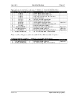
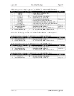
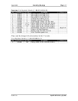
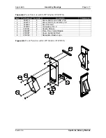
Table A-1:

 Apollo Ink Delivery System, 4”, BK660, 6’, NA (660-IDM4H-06NA) 

Item 

Part Number 

Quantity 

Description 

Reference 

404510 

Screw, BHCS, 10-32 UNF x ¼” 


404520 

Screw, BHCS, 10-32 UNF x 3/8” 


606322 

Cord, Set, 10A/125 VAC, 90”, N.A., IEC 


4 615140  6 

Lashing 

Tie, 

Small 


9101776 

58” 

Sleeving, Braided, Expandable 


9102603 

2 x 2” 

Shrink Wrap, 1 ½” OD, ½” ID 


9103243A 

HP Regulator Mount Assembly 

Page A-19 

9103565A 

Cable, Ribbon, DB9 Male to Female, 65” 


9103599 

Bracket, Apollo IDM, BK660 


10 

BK-BULKPRIME 

Syringe Assembly, Apollo Bulk Ink 

Page A-11 

11 

BK-BULKREG-06 

Regulator Module, Apollo 6’ 

Page A-12 

12 

BK-IDM-4H 

Module, Apollo Ink Delivery, 4-Channel 

Page A-14 

13 

BKINK-VERBKPEN 

Ink, HP Cartridge, Bulk, Versatile Black 


Please note the changes in each item number for the different kinds of systems:  
 

Apollo Ink Delivery, System, 2”, BK660, 6’, NA (660-IDM2H-06NA) 

Item 

Part Number 

Quantity 

Description 

Reference 

11 

BK-BULKREG-06 

Regulator Module, Apollo 6’ 

Page A-12 

13 

BKINK-VERBKPEN 

Ink, HP Cartridge, Bulk, Versatile Black 


Buskro Ltd. 


Apollo Ink Delivery System


Содержание Apollo BK-IDM-4H

Страница 1: ...Apollo Ink Delivery System Part No 9103326 User s guide V1 2 ...

Страница 2: ...olation of copyright laws Copyright 2004 Buskro Ltd First Edition 2004 Printed in Canada This manual is sold as is without warranty of any kind either express or implied respecting the contents of this manual including but not limited to implied warranties for the manual s quality performance merchantability or fitness for any particular purpose Neither Buskro Ltd nor its dealers or distributors s...

Страница 3: ...2 4 2 2 Ink Delivery Module 2 6 2 2 1 BK460 660 Controller Installation 2 6 2 2 1 1 Attaching the IDM bracket to the BK460 660 Controller 2 7 2 2 1 2 Securing the IDM into the BK700 IDM bracket 2 8 2 2 2 BK700 Controller Installation 2 8 2 2 2 1 Attaching the IDM bracket to the BK700 Controller 2 8 2 2 2 2 Securing the IDM into the BK700 IDM bracket 2 10 2 2 3 BK760 System Installation 2 11 2 2 3 ...

Страница 4: ...N INK Condition 3 2 3 2 2 INK OUT Condition 3 3 3 3 Ink Cartridge 3 3 3 3 1 Inserting an Ink Cartridge into the IDM 3 4 3 3 2 Removing an Ink Cartridge from the IDM 3 5 3 3 2 1 Activating the Ink Delivery System 3 5 3 3 3 Cartridge Replacement 3 5 3 3 3 1 Replacing an empty ink cartridge 3 6 3 4 Ink Pen Assembly 3 6 3 4 1 Pen Replacement 3 7 3 4 1 1 Replacing a defective ink pen 3 7 4 0 Printhead ...

Страница 5: ...General Information Chapter 1 1 0 General Information Buskro Ltd Apollo Ink Delivery System ...

Страница 6: ...ovided via a universal IEC connector with input voltage ranging between 100 240 V 50 60 Hz The system is comprised of 3 major elements including the following Ink Delivery Module Operator accessible module that pumps and delivers ink from a single 350 mL ink cartridge into a common 4 channel manifold for distribution to a maximum of 8 ink pens over a maximum distance of 15 Regulator Module A unit ...

Страница 7: ... On the Fly Refill and Level Sensing The replaceable 350 ml ink cartridge is equipped with level sensing that alerts the operator for on the fly removal and replacement during operation 1 2 4 Common Ink Distribution The Ink Delivery Module features a common manifold that distributes ink up to a total of 8 ink pens ensuring uniform ink fill to all ink pens for reduced individual failure 1 2 5 Reduc...

Страница 8: ... kg 9 4 lbs Ink Pen 0 20 kg 0 44 lbs Ink Cartridge 0 61kg 1 35 lbs 1 3 4 Electrical requirements Line Voltage 100 240 V 50 60 Hz Line Current 0 3 Amps maximum Power 20 W 1 3 5 Operator controls Main Power Switch Main Power 1 3 2 Ink Cartridge and Pen Specifications Item Specification Note Vertical Resolution 600 DPI Horizontal Resolution 150 200 300 400 600 DPI Software selected Ink Supply Ink Car...

Страница 9: ...rate at either a 600 or 660 native resolution The resolution used on a particular system depends on the encoder arrangement 2 The Production value is based on a No 10 envelope 9 5 Long with a 1 5 gap between pieces Longer pieces would decrease the production rate The production rating is based on operating frequencies and is the theoretical maximum based on software constraints Actual production r...

Страница 10: ... Components 700 IDM4H 06NA shown Item Description Part Number 1 Ink Cartridge HP Versatile Black 350 mL BKINK VERBK350 2 Apollo Ink Delivery Module 4 Channel BK IDM 4H 3 Bracket Ink Delivery Module BK700 9103267 4 Regulator Module 6 BK BULKREG 06 5 Bracket Regulator Module 9103243A 6 Ink Pen Bulk HP Versatile Black 42mL BKINK VERBKPEN 7 Cable IDM Serial Communication BK CAB IDMCOM 8 Cable IEC Type...

Страница 11: ...e 1 2 Apollo Ink Delivery Module Dimensions Symbol Description Dimensions I W IDM Overall Width 4 02 102 mm I L IDM Overall Length 12 13 308 mm I H IDM Overall Height 10 48 266 mm X1 Supply Station Extension 1 34 34 mm C L Casing Length 9 99 254 mm C H Casing Height 9 35 237 mm Buskro Ltd Apollo Ink Delivery System ...

Страница 12: ...eight 2 69 68 mm L1 Ink Line To IDS Length 6 or 15 1 83m or 4 57 m L2 Ink Line To Ink Pens Length 24 610 mm L1 X1 I W I H I L Quick Disconnect Fittings Figure 1 4 Ink Pen Bulk Versatile Black 42 mL Dimensions Table 1 4 Ink Pen Bulk Versatile Black 42 mL Dimensions Symbol Description Dimensions I W Ink Pen Overall Width 3 90 99 mm I L Ink Pen Overall Length 0 70 18 mm I H Ink Pen Overall Height 4 2...

Страница 13: ...dge Versatile Black 350 mL Dimensions Table 1 5 Ink Cartridge Versatile Black 350 mL Dimensions Symbol Description Dimensions B W Ink Cartridge Overall Width 2 04 52 mm B L Ink Cartridge Overall Length 6 52 166 mm B H Ink Cartridge Overall Height 4 37 111 mm Buskro Ltd Apollo Ink Delivery System ...

Страница 14: ...Ink Delivery System Installation Chapter 2 2 0 Ink Delivery System Installation Buskro Ltd Apollo Ink Delivery System ...

Страница 15: ...gulator modules up to 4 are installed on a bracket that attaches to the end of a print head bridge or directly onto a base The steps required to install the Regulator Module s are as follows 1 Attach the regulator module bracket 2 Set the height of the Regulator Module 3 Attach the ink lines to the ink pen and ink delivery module 2 1 1 Mounting the Regulator Module Bracket 2 1 1 1 Mounting onto a ...

Страница 16: ...racket and mount together 3 Place the regulator bracket onto the bridge and ensure the bottom of the bracket is about 0 83 to 1 83 above the printhead nozzles Use the two longer screws SHCS 5 16 18 UNC to secure it in place Figure 2 2 4 Place the regulator mount back onto bracket Figure 2 2 Attaching Regulator Assembly to the bridge Buskro Ltd Apollo Ink Delivery System ...

Страница 17: ... mount holding the regulators is adjustable Remove the two screws and reattach them to the plate through the two vertical slotted holes located on the sides of the bracket Figure 2 3 2 Then mount the assembly to the tabletop using a 20 UNC SHCS screw through one of the holes that are available as shown in Figure 2 4 for the BK460 tabletop and Figure 2 5 for the BK660 tabletop Mount to either one o...

Страница 18: ... it could lead to low drop volumes and de priming of the ink pen Conversely placing the regulator above the recommended height could cause the ink to leak out of the ink pen The regulator module s are mounted on a regulator module bracket See instruction 2 1 1 equipped with mounting slots for height adjustment They can be adjusted in two ways one by adjusting the height of the mounting assembly al...

Страница 19: ...ator module is 0 83 21 mm to 1 83 46 5 mm above nozzle plate level for proper ink pen operation Figure 2 7 Adjusting the Regulator module bracket height along the bridge Figure 2 8 Adjusting the Regulator module mount height along the bracket Buskro Ltd Apollo Ink Delivery System ...

Страница 20: ...ed directly into a rack The steps required to install the Ink Delivery Module s are as follows 1 Attach the ink delivery module bracket to the controller 2 Secure the IDM on the bracket or rack 3 Attach the ink line s to the regulator module s 4 Attach the power cord and serial communication cables Note The IDM should always be placed to the right of any controller if a choice is given by default ...

Страница 21: ...through the rectangular slot 4 Line up the holes of the bracket with those on the top of the controller console 5 Reattach the two monitor brackets back into place Figure 2 10 6 Place the monitor back on top and reattach its cables 7 Ensure the serial cable and power cable are attached to the back of the system Figure 2 21 8 Route all cables except for the IDM s power cable through the same rectan...

Страница 22: ...et to the BK700 Controller Figure 2 11 Apollo IDM mounted on a BK700 Controller Bracket permits mounting on either side 1 If an existing HP Reservoir already exists on your system loosen the two screws on each side of the controller that hold the reservoir in place DO NOT remove the screws completely and slide the reservoir out as shown in Figure 2 12 Tighten the screws back down EXISTING HP RESER...

Страница 23: ...ure 2 13 Mounting bracket for BK700 Controller 5 Re tighten the four screws onto the controller 6 Ensure the serial cable is attached to the back of the system Figure 2 21 7 Route the serial cable through the center opening on the top of the controller box See Figure 2 14 8 Take the power cable and route the IEC end of it through the same center opening from the bottom up Attach the power cable to...

Страница 24: ...on cables through the top of the controller box 2 2 2 2 Securing the IDM into the BK700 IDM bracket 1 Place the Apollo IDM on the IDM mounting bracket 2 Use the two screws p n 404510 to secure the IDM in place as shown in Figure 2 15 Figure 2 15 Securing the Apollo IDM to the BK700 IDM bracket Buskro Ltd Apollo Ink Delivery System ...

Страница 25: ...itor If two IDM brackets are installed place the second bracket on top of the first except on the opposite side of the monitor 4 Re install the monitor tray 5 Line up the holes and replace the four screws with the longer 10 32 UNF screws included and tighten it down into place Figure 2 16 6 Ensure the serial cable and power cable are attached to the back of the module s Figure 2 21 7 Route the ser...

Страница 26: ...Ink Delivery System Installation Page 2 12 Figure 2 16 Attaching the Apollo IDM bracket to the BK760 monitor tray Figure 2 17 Securing the Apollo IDM to the BK760 IDM bracket Buskro Ltd Apollo Ink Delivery System ...

Страница 27: ...Chapter 2 Ink Delivery System Installation Page 2 13 ROUTE SERIAL CABLE THROUGH HERE Figure 2 18 Routing of the Serial Cable in BK760 Buskro Ltd Apollo Ink Delivery System ...

Страница 28: ...ontroller Be sure to place it as far left as possible Covers may have to be removed for this operation 2 Secure the IDM to the rack by using the screws that are already in place on the top and bottom of the IDM 3 Ensure the serial cable and power cable are attached to the back of the system Figure 2 21 4 Route both serial and power cable along the side of the controller The side door should be ope...

Страница 29: ...l cable In addition to the physical connection of the communication cable some software setup in Compose will be required to identify the physical serial port used by the IDM Please use Figure 2 21 to help identify the various locations of where each cable attachment should be used The steps required to connect the power and serial cables are as follows 1 Connect the power cable into a power sourc...

Страница 30: ... Delivery System Installation Page 2 16 4 Channel Ink Port IEC Power Receptacle RS232 Connector DB9 Alarm Connector Ink Delivery Module Figure 2 21 Location of Cable Attachments Buskro Ltd Apollo Ink Delivery System ...

Страница 31: ... BK700 controller Figure 2 22 Power Box Assembly Figure 2 22 Attachment point power bar for the power cable on BK700 controller 2 3 1 3 BK760 Power Cable The power cable for the IDM should be attached separately from the controller to an external power outlet 2 3 1 4 BK1700 Power Cable The power cable for the IDM should be attached to the power supply module p n BK PSM 4H of the BK1700 controller ...

Страница 32: ...nection is made Compose IQ inkjet control software will have to know where the connection has been made by identifying the port used In addition the Windows device manager will have to be configured to define the COM port 2 4 1 RS232 COM Serial Cable Connection 2 4 1 1 Serial Ribbon Cable Attachment 1 Ensure the controller s power is OFF 2 Attach the serial ribbon cable into an available motherboa...

Страница 33: ...If they are enable them by selecting an address for each COM port Ensure that these addresses are unique for each port 5 Save and exit setup 6 Once completed allow Windows to start 7 Go to the start menu 8 Enter the control panel 9 Double click on the system icon Figure 2 24 10 Click on the hardware tab and click on Device Manager button 11 Under Ports COM LPT if a red X is marked on each of the C...

Страница 34: ...Chapter 2 Ink Delivery System Installation Page 2 20 Figure 2 24 System Icon in the control panel Figure 2 25 Enabling Serial Ports in the Device Manager Buskro Ltd Apollo Ink Delivery System ...

Страница 35: ...are on a CD has been provided See Figure 2 26 Figure 2 26 Inserting the Serial to USB Cable into an available USB port of the motherboard 2 4 2 2 Serial to USB Cable Software Setup 1 Follow the step by step manual that comes with the cable to install its drivers 2 Go to the Start menu 3 Enter the control panel 4 Double click on the System icon 5 Click on the Hardware tab and click on Device Manage...

Страница 36: ...rial Cable Setup to Comtrol RocketPort Card In the event there are no available RS232 serial or USB ports a separate Serial Communication Card p n BK COMM will have to be used Note In general for Compose IQ advanced applications this board may already be installed OCR selective slave This option is not available for BK760 systems 1 Follow the step by step instructions included with the Serial Comm...

Страница 37: ...configured to use the serial ports you will now have to set up Compose to ensure the correct COM port has been assigned for IDM use 1 Open Compose and click on the Setup icon 2 Click on the Options tab and go to Advanced settings 3 Ensure that HP Ink ports have been set to the COM port used by the IDM communication cable See Figure 2 28 4 Click OK exit Compose and Restart the computer Figure 2 28 ...

Страница 38: ... Compose IQ Each Apollo Ink Delivery System needs to be assigned to a series of 4 print bars i e for a 2 Apollo Ink Delivery System say A B system A will need to be assigned to print bars 1 4 and system B will need be assigned to print bars 5 8 This can be modified by performing the following steps in the setup menu 1 Open the setup dialog box Figure 2 29 in Compose IQ and click on the Print Heads...

Страница 39: ...lly connected in a system s configuration In order to have both IDSs initialize you will also need to assign print bars 5 8 so that both units are being used 2 6 Installing Module Ink Lines 1 For the BK1700 only Route the regulator inkline umbilical through the closest slotted hole in the back of the controller Then attach the umbilical clamp to hold the umbilical in place Figure 2 31 2 Remove the...

Страница 40: ...lation Page 2 26 Route umbilical through here Figure 2 31 Routing the regulator ink lines through the BK1700 controller Figure 2 32 Inserting the regulator ink line connectors into the back of the IDM Buskro Ltd Apollo Ink Delivery System ...

Страница 41: ... in Figure 2 33 Figure 2 33 Insertion of Ink Pen into the individual Apollo pen stalls 3 Lift up the desired blue pen latch on the Apollo head 4 Insert the Ink Pen into the designated slot as shown in the upper pen of Figure 2 34 5 Press down on the pen latch until it has snapped on top of the ink pen shown in the lower pen of Figure 2 34 6 Connect the ink line from the ink pen to the regulators f...

Страница 42: ...of Ink Pen into the individual Apollo pen stalls 2 7 2 Ink Pen Removal 1 Lift up the blue tab of the ink pen that is being removed and fold it back completely as shown in the upper pen of Figure 2 34 2 Remove the ink pen from the printhead Buskro Ltd Apollo Ink Delivery System ...

Страница 43: ...attach the priming tool to the regulators To attach the quick disconnects fittings together 1 Press and hold down on the white triangular tab of the female connector 2 While holding down the tab insert the male connector 3 Once completely inserted release the tab 4 To disconnect the fittings simply press the white tab The male end should be ejected Figure 2 35 Connecting the regulator ink line to ...

Страница 44: ...rror has occurred See Figure 2 36 The connector has both normally open and normally closed contacts to control the alarm module It also has a 12 VDC power supply if it is required to power the alarm Please refer to Figure 2 37 and Table 2 1 for the description of each pin Alarm Connector Figure 2 36 Location of the 6 pin alarm Connector at the back of the IDM 2 1 4 3 Terminal Pins N C Switch 12 VD...

Страница 45: ...Common 1 3 12 VDC 4 GND 5 Common 2 6 Switch 2 Normally Open Note If you intend to attach an electrical warning device to this output please consult with Buskro LTD The Weidmuller part numbers that mate with this connector are the following BLC 5 08B BLIDC 5 08B BLT 5 08B BLZ 5 08B and BLZF 5 08B Buskro Ltd Apollo Ink Delivery System ...

Страница 46: ...Operating Instructions Chapter 3 3 0 Operating Instructions Buskro Ltd Apollo Ink Delivery System ...

Страница 47: ... via a 6 pin connector for those users wishing to add an external alarm device Note The system will only function with Buskro ink cartridges Ink cartridges purchased elsewhere will not enable the system to commence the ink pumping operation 3 2 Front Panel Indicators Situated on the front of the IDM above the cartridge stall is a series of 5 indicator LEDs that show the state of the system Indicat...

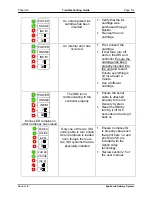
Страница 48: ...NK OUT Unrecognized Cartridge ON when an unrecognized cartridge is used i e from another supplier Only Buskro cartridges will work Cartridge Error No Ink ON when there is a cartridge error i e bad electrical connection burst bag smart chip problem etc or an Ink Out condition no more ink When the IDM is out of ink both the Cartridge Error and Ink Low LED will be ON 3 2 1 LOW ON INK Condition To tel...

Страница 49: ...eplaced ONLINE INK POWER Figure 3 3 INK OUT Condition 3 3 Ink Cartridge The ink cartridge contains 350 mL of ink enough ink to refill one ink pen over eight times These cartridges can only be used once and must be purchased through Buskro LTD Ink cartridges purchased elsewhere will not work with this system Note The system will only function with Buskro ink cartridges Ink cartridges purchased else...

Страница 50: ...he back Then push the cartridge downward until it is latched into place Figure 3 5 3 After a 5 to 10 second delay in which the controller is reading and validating the cartridge the ONLINE indicator should go ON and activate the pump 4 In the event an error or unrecognized cartridge is detected the pump will not operate and the system will remain OFFLINE Try another ink cartridge and or refer to T...

Страница 51: ...e removal procedure from the IDM cartridge stall 3 3 2 1 Activating the Ink Delivery System Note The system will only function with Buskro ink cartridges Ink cartridges purchased elsewhere will not enable the system to commence the ink pumping operation 1 If a cartridge is not present follow the instructions listed in section 3 3 1 2 Turn ON the Power switch Figure 1 1 3 Turn on the controller and...

Страница 52: ...2 Remove the empty ink cartridge by following the instructions cited in section 3 3 2 3 Insert a new ink cartridge by following instructions in Section 3 3 1 4 Ensure the system is properly activated as outlined in instructions 3 3 2 1 3 4 Ink Pen Assembly The ink pen assembly includes an ink pen and an interconnect tube assembly Figure 3 7 Both the ink pen and interconnect tube assembly are fille...

Страница 53: ...e troubleshooting procedures outlined in Table 5 1 If this does not solve the problem then the ink pen should be replaced Note The ink pen is designed for 8 to 10 refills about 1 ink cartridge 3 4 1 1 Replacing a defective ink pen 1 Stop the operation of the transport system 2 Remove the ink pen by following the instructions cited in section 2 7 2 3 Insert a new ink cartridge by following instruct...

Страница 54: ...Printhead Maintenance Chapter 4 4 0 Printhead Maintenance Buskro Ltd Apollo Ink Delivery System ...

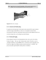
Страница 55: ...ad scratching Fibreless to avoid small fibres from blocking the nozzles No chemical additives Note Never use industrial paper towels toilet paper or sponges to wipe the ink pens This can result in permanent damage to the ink pens 4 1 1 Ink Pen Cleaning There are two main methods of cleaning the ink pens Each individual ink pen can be removed from the stall and wiped or the entire print head assemb...

Страница 56: ...he interconnect pad is dry before reinserting the ink pen back into the printhead otherwise an electrical shortage may occur resulting in permanent damage 4 1 3 Printhead Purging If the printhead is inactive for an extended period of time ink may dry in the nozzles forming ink plugs This may result in missing lines of print When this occurs the cartridges should first be wiped Section 4 1 1 Once t...

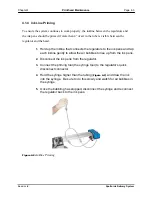
Страница 57: ...ap each inkline gently to allow the air bubbles to rise up from the ink pens 2 Disconnect the ink pens from the regulator 3 Connect the priming tool the syringe tool to the regulator s quick disconnect connector 4 Hold the syringe higher than the tubing Figure 4 2 and draw the ink into the syringe Be sure to do this slowly and watch for air bubbles in the syringe 5 Once the bubbling has stopped di...

Страница 58: ...ly free of dust and paper particles In addition the storage area should not be dry Note One option for long term ink pen storage is to place the pens in a Tupperware container with a damp sponge or towel to maintain humidity This will help prevent the printhead from drying out 4 2 Lifetime of Components Please note that each regulator has been tested to work up to 30L of ink As well each pen has a...

Страница 59: ...Troubleshooting Guide Chapter 5 5 0 Troubleshooting Guide Buskro Ltd Apollo Ink Delivery System ...

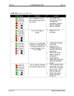
Страница 60: ...underneath the printhead Confirm Compose is set to enable printing Wipe and purge printhead Re insert the ink pen into the printhead Install a new ink cartridge Ensure the tape is off the ink pen Re insert the ink cartridge into the IDM Ensure the regulator assembly is set at the correct height Section 2 1 1 2 Ensure the IDM is online Missing lines streaks in text or graphics Wipe and purge printh...

Страница 61: ...roperly with as much as 4 inches of visible air in the tube Connect the system and use it to print Prime the inkline Ink is seeping from the nozzles Verify that the regulator assembly is at the correct height Section 2 1 1 2 Text characters and graphic are light Verify that the regulator assembly is at the correct height Section 2 1 1 2 Replace ink pens Buskro Ltd Apollo Ink Delivery System ...

Страница 62: ...K POWER There is no ink cartridge Compose is currently not running or there is no serial connection The unit is offline Verify that Compose is running Ensure an ink cartridge has been inserted Reinsert if necessary Ensure the serial cable is properly connected Verify that the controller s serial port has been properly set up ONLINE INK POWER The Ink Delivery Module has not been powered on Verify a...

Страница 63: ...erent cartridge ONLINE INK POWER Online LED remains on after Compose has closed The IDM is not communicating to the controller properly Ensure the serial cable is attached properly to the Ink Delivery System Reset the IDM by turning it off for 5 seconds and turning it back on ONLINE INK POWER ONLINE INK POWER Only one of the two IDS units is able to turn online when Compose is loaded even though t...

Страница 64: ...ly 9103298A A 20 Table A 13 Upper Bracket Assembly HP Module 9103479A A 21 Table A 14 Cable Power Input Switched Apollo Module 9103609A A 23 List of Figures Figure A 1 Apollo Ink Delivery System 4 BK660 6 NA 660 IDM4H 06NA A 4 Figure A 2 Apollo Ink Delivery System 4 BK700 6 NA 700 IDM4H 06NA A 6 Figure A 3 Apollo Ink Delivery System 4 BK760 6 760 IDM4H 06NA A 8 Figure A 4 Apollo Ink Delivery Syste...

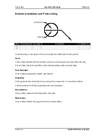
Страница 65: ...ue part in an assembly drawing It is matched with the top number in the balloon pointing at the associated part Part Number This column represents the Buskro part number Quantity This represents the total number of a given part in an assembly It is matched with the bottom number in the balloon pointing at the associated part Description This column contains a brief description of the part Referenc...

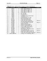
Страница 66: ...able Ribbon DB9 Male to Female 65 9 9103599 1 Bracket Apollo IDM BK660 10 BK BULKPRIME 1 Syringe Assembly Apollo Bulk Ink Page A 11 11 BK BULKREG 06 4 Regulator Module Apollo 6 Page A 12 12 BK IDM 4H 1 Module Apollo Ink Delivery 4 Channel Page A 14 13 BKINK VERBKPEN 8 Ink HP Cartridge Bulk Versatile Black Please note the changes in each item number for the different kinds of systems Apollo Ink Del...

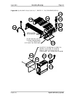
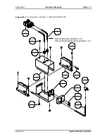
Страница 67: ...ABOVE THE BOTTOM OF THE PRINTHEAD USE THE BRAIDED SLEEVING 9101776 TO TIE TUBES TOGETHER LEAVE 7 OF THE TUBING EXPOSED ON EACH END FOR BRIDGE LENGTHS OF 22 OR LESS CUT 24 OFF THE TUBE BEFORE INSTALLING THE CONNECTOR MONITOR BRACKET SHOWN FOR REFERENCE MONITOR BRACKET SHOWN FOR REFERENCE 9 1 12 1 3 1 8 1 4 6 5 1 6 2 11 4 13 8 10 1 7 1 1 2 2 4 2 4 Buskro Ltd Apollo Ink Delivery System ...

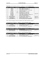
Страница 68: ... 14 12 BKINK VERBKPEN 8 Ink HP Cartridge Bulk Versatile Black Please note the changes in each item number for the different kinds of systems Apollo Ink Delivery System 2 BK700 6 NA 700 IDM2H 06NA Item Part Number Quantity Description Reference 10 BK BULKREG 06 2 Regulator Module Apollo 6 Page A 12 12 BKINK VERBKPEN 4 Ink HP Cartridge Bulk Versatile Black Apollo Ink Delivery System 2 BK700 15 NA 70...

Страница 69: ...0 4 BRIDGE SHOWN FOR REFERENCE MOUNTS TO THE BRACKET HOLDING THE INKWELL ON THE SIDE OF THE BK700 DEFAULT SIDE IS THE RIGHT SIDE OF CONTROLLER LEFT VERSION SHOWN HERE MOUNT THE REGULATOR SO THAT THE BOTTOM IS 1 0 TO 2 0 ABOVE THE BOTTOM OF THE PRINTHEAD 9 1 5 1 4 2 3 1 8 1 7 1 11 1 6 1 Buskro Ltd Apollo Ink Delivery System ...

Страница 70: ...N 8 Ink HP Cartridge Bulk Versatile Black Please note the changes in each item number for the different kinds of systems Apollo Ink Delivery System 4 BK760 6 WD 760 IDM4H 06WD Item Part Number Quantity Description Reference 3 9103256 1 Cord 10A 250 VAC 3m Harmonized IEC 10 BK BULKREG 06 2 Regulator Module Apollo 6 Page A 12 12 BKINK VERBKPEN 4 Ink HP Cartridge Bulk Versatile Black Apollo Ink Deliv...

Страница 71: ...ystem 4 BK760 6 760 IDM4H 06NA 1 2 4 6 13 8 3 1 12 1 8 1 10 1 11 4 7 1 9 1 5 1 6 2 2 4 BRIDGE SHOWN FOR REFERENCE MOUNT THE REGULATOR SO THAT THE BOTTOM IS 1 0 TO 2 0 ABOVE THE BOTTOM OF THE PRINTHEAD MONITOR TRAY SHOWN FOR REFERENCE Buskro Ltd Apollo Ink Delivery System ...
Страница 72: ... HP Cartridge Bulk Versatile Black Please note the changes for each item number for the different kinds of systems Apollo Ink Delivery System 2 BK1700 6 NA 1700 IDM2H 06NA Item Part Number Quantity Description Reference 9 BK BULKREG 06 2 Regulator Module Apollo 6 Page A 12 11 BKINK VERBKPEN 4 Ink HP Cartridge Bulk Versatile Black Apollo Ink Delivery System 2 BK1700 15 NA 1700 IDM2H 15NA Item Part ...

Страница 73: ...Apollo Ink Delivery System 4 BK1700 6 1700 IDM4H 06NA 9 4 BRIDGE SHOWN FOR REFERENCE MOUNT THE REGULATOR SO THAT THE BOTTOM IS 1 0 TO 2 0 ABOVE THE BOTTOM OF THE PRINTHEAD 8 1 2 1 7 1 10 1 4 1 5 2 3 6 1 4 6 1 11 8 Buskro Ltd Apollo Ink Delivery System ...
Страница 74: ...cription Reference 1 9100145 1 T Connector 1 8 2 9100472 2 Tubing Silicone OD x 1 8 ID 3 9101292 1 Syringe 30 cc 4 9103061 2x 4 Tubing LDPE 1 8 ID x 3 16 OD 90 Duro 5 9103303 2 Coupling Body Male 1 8 O D NS4 Figure A 5 Syringe Assembly Apollo Bulk Ink BK BULKPRIME 5 2 1 1 4 2 2 1 3 1 5 2 Buskro Ltd Apollo Ink Delivery System ...

Страница 75: ...03059 2 x 1 Tubing LDPE 3 32 ID x 5 32 OD 90 Duro 8 9103061 2 x 48 Tubing LDPE 1 8 ID x 3 16 OD 90 Duro 9 9103061 72 Tubing LDPE 1 8 ID x 3 16 OD 90 Duro 10 9103067A 1 Manifold Block Regulator Inlet Assembly Page A 18 11 9103244 1 Chassis HP Hybrid Regulator 12 9103246 2 Bushing Snub 3 8 OD x 3 16 I D 13 9103265 1 Cover Hybrid Regulator Unit Please note the changes in the item number for the 15 sy...

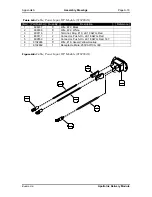
Страница 76: ...Drawings Page A 13 Figure A 6 Unit Regulator Module 6 BK BULKREG 06 10 1 7 2 9 1 4 1 5 2 3 2 2 6 12 2 2 6 6 2 FOR 39 BRIDGE LENGTH 48 FOR 22 BRIDGE OR LESS LENGTH 24 13 1 1 2 8 2 11 1 Buskro Ltd Apollo Ink Delivery System ...

Страница 77: ...2341A 1 Cable Hybrid IDS board I O 14 9102862A 1 Cable Power Input HP Module Page A 16 15 9102995 1 Ink Supply Station Modular Hybrid 16 9102997A 1 Front Panel Assembly HP Module Page A 17 17 9102998 1 Bracket HP Module 18 9103024 1 Support Hybrid Shell Mount 19 9103049 1 Bracket Controller Module Top 20 9103054 2 Cover Controller Module Side 21 9103059 3 Tubing LDPE 3 32 ID x 5 32 OD 22 9103254A ...

Страница 78: ... 1 27 1 Note When attaching the tubing 9103059 to the Ink Supply Station insert it directly into the port without removing the rubber ring or the plastic clamp already in place 17 1 13 1 3 2 6 6 8 6 25 1 2 4 15 1 6 6 8 6 19 1 5 14 5 14 20 2 18 1 9 1 10 2 7 2 5 14 14 1 1 2 2 4 22 1 11 2 26 1 5 14 21 1 Buskro Ltd Apollo Ink Delivery System ...

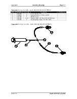
Страница 79: ...2 606038 5 Wire 22 White 3 609116 1 Terminal Ring 10 22 18 AWG Red 4 609117 2 Connector Push On 22 18 AWG Red 5 609530 2 Connector Push On 22 18 AWG Red 187 6 9102246 5 Wire 18 Green Yellow Hookup 7 9102862 1 Receptacle Male 250VAC 10A IEC Figure A 8 Cable Power Input HP Module 9102862A L N GND 5 2 1 1 2 1 6 1 3 1 4 2 7 1 Buskro Ltd Apollo Ink Delivery Module ...

Страница 80: ...S 6 32 UNC x 1 4 2 404010 2 Screw FHCS 10 32 UNF x 1 4 3 420006 4 Nut 6 32 UNC 4 439006 4 Lockwasher No 6 5 9102941 2 Handle Module 6 9102997 1 Plate Front Hybrid Module 7 9103027 1 Cover Hybrid Ink Shell 8 9103183 1 Nameplate Buskro Logo Figure A 9 Front Panel Assembly HP Module 9102997A 5 2 8 1 6 1 1 4 2 2 7 1 4 4 3 4 Buskro Ltd Apollo Ink Delivery Module ...

Страница 81: ...ion Reference 1 404510SS 1 Screw BHCS 10 32 UNF x SS 2 9103067 1 Manifold Block Hybrid Regulator Inlet 3 9103304 1 Fitting 10 32 UNF 1 8 I D PP 4 9103305 2 Fitting 10 32 UNF 3 32 I D PP Figure A 10 Manifold Block Regulator Inlet Assembly 9103067A USE TEFLON TAPE FOR THREAD SEALANT 3 1 2 1 4 2 1 1 Buskro Ltd Apollo Ink Delivery Module ...

Страница 82: ...9103243A Item Part Number Quantity Description Reference 1 404510 2 Screw BHCS 10 32 UNF x 1 4 2 9103243 1 Bracket Hybrid Regulator Height Adjust 3 9103266 1 Mount HP Regulator Unit Figure A 11 HP Regulator Mount Assembly 9103243A 2 1 3 1 1 2 Buskro Ltd Apollo Ink Delivery Module ...

Страница 83: ...103298 1 Manifold Block Hybrid Module Out 4 9103300 4 Check Valve Cart 3 8 OD 1 2 PSI 5 9103306 1 Fitting Elbow 10 32 UNF 3 32 I D PP 6 9103319 4 Adapter 1 4 NPT Male x 1 8 NPT Female Figure A 12 Manifold Block Hybrid Out Assembly 9103298A 4 4 6 4 2 4 APPLY THREAD SEALER THE END OF THE CHECK VALVE WITH THE VISIBLE SPRING SHOULD FACE TOWARDS THE CENTRE OF THE MANIFOLD 5 1 3 1 1 1 Buskro Ltd Apollo ...

Страница 84: ...Silicone 1 4 OD x 1 8 ID 9 9100472 2 Tubing Silicone 1 4 OD x 1 8 ID 10 9100472 1 Tubing Silicone 1 4 OD x 1 8 ID 11 9100921 1 Lung Vacuum Pump 12 9100971 1 Gripper Clip 13 9101290 1 Fitting Tee 1 8 I D 14 9101582 1 Fitting 10 32 Thread to Tube 1 8 I D 15 9102246 6 Wire 18 Green Yellow Hookup 16 9102417 1 Power Supply Switching 12VDC 1 7A 17 9102960 1 Valve Flow Control 10 32 UNF 18 9102994 1 Boar...

Страница 85: ...age A 22 Figure A 13 Upper Bracket Assembly HP Module 9103479A A 13 1 8 1 11 1 12 1 9 1 10 1 18 1 22 1 3 4 14 1 2 2 17 1 21 1 20 1 19 1 16 1 1 4 SET THE FLOW CONTROL VALVE TO A PRESSURE OF 5 PSI Buskro Ltd Apollo Ink Delivery Module ...

Страница 86: ... 3 609530 2 Connector Push On 22 18 AWG Red 187 4 9102564 1 Connector Female 4 Pin 5264 5 9102565 2 Contact Female 22 28 SPOX 6 9102772 2 Keying Plug Universal Polarizing Pin Figure A 14 Cable Power Input Switched Apollo Module 9103609A 1 Black Line 2 Keying Plug 3 4 White Pin Colour Function Keying Plug Neutral 4 1 GLUE KEYING PLUGS INTO PIN 2 AND 3 3 2 1 1 2 1 5 2 6 2 4 1 Buskro Ltd Apollo Ink D...

Страница 87: ...Electrical Drawings Appendix B B 0 Electrical Drawings List of Schematics Figure B 1 Electrical Schematic HP Hybrid Rackmount 9102998AE B 2 Buskro Ltd Apollo Ink Delivery System ...

Страница 88: ...Appendix B Electrical Drawings Page B 2 Figure B 1 Electrical Schematic HP Hybrid Rackmount 9102998AE Buskro Ltd Apollo Ink Delivery System ...
Отзывы: