


8
SecTiON iii – iNSTALLATiON iNSTRUcTiONS
equipment in space. Duct cross-sectional area
shall be same as opening free area.
3. Horizontal ducts. Minimum free area of 1
square inch per 2,000 Btu per hour input of all
equipment in space. Duct cross-sectional area
shall be same as opening free area.
Alternate method for boiler located within
confined space.
Use indoor air if two permanent
openings communicate directly with additional
space(s) of sufficient volume such that combined
volume of all spaces meet criteria for unconfined
space. Size each opening for minimum free area
of 1 square inch per 1,000 Btu per hour input of
all equipment in spaces, but not less than 100
square inches.
4. LOUVERS AND GRILLES of Ventilation Ducts
All outside openings should be screened and louvered.
Screens used should not be smaller than ¼ inch mesh.
Louvers will prevent the entrance of rain and snow.
a. Free area requirements need to consider the blocking
effect of louvers, grilles, or screens protecting the
openings. If the free area of the louver or grille
is not known, assume wood louvers have 20-25
percent free area and metal louvers and grilles have
60-75 percent free area.
b. Louvers and grilles must be fixed in the open
position or interlocked with the equipment to open
automatically during equipment operation.
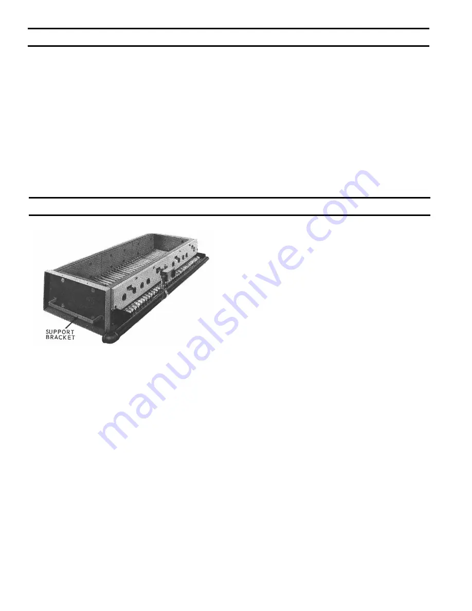
FIG. 2
SINGLE MANIFOLD BASE 5006B
THRU 5014B SECTION BOILERS
1
. BASE-BURNER-MANIFOLD ASSEMBLY(S).
a. 5006B section thru 5014B section boilers require
single base assembly, see Fig. 2.
b. 5015B section thru 5026B section boilers require a
left and a right base subassembly, see Fig. 3.
Remove Base Assembly(s) From Skid(s)
c. Remove bolts securing Base Assembly(s) to
shipping skid(s) and place Base(s) in location where
Boiler is to be installed.
d. Join Base Sub-assemblies together (15 section &
larger boilers) by first removing upper shipping
strip and lower shipping angles from subassemblies.
Use (4) ¼”-20 x ¾” MS, nuts and washers to attach
subassemblies, see Fig. 3.
e. Attach Front Intermediate Jacket Panel Support
Bracket and Lower Rear Intermediate Panel Support
Bracket to lower channel on Front Base Frame and
Rear Base Frame, respectively, using (4) ¼”-20 x
¾” MS, nuts and washers.
f. Base must be level in both directions and secure on
the floor. Shim and grout under Base if necessary.
g. Place cardboard covering over the top of the burner
assembly to protect them during the assembly of the
boiler sections.
2.
CLEAN BOILER SECTIONS inside and out to remove
dirt due to shipment and handling.
Open Tie Rod Bundle(s). Open Draw-up Rod
Bundle(s
).
Open Boiler Assembly Carton(s).
3.
SET LEFT END SECTION ON BASE so that locating
lugs on bottom of section go inside Front and Rear Base
Frames. Slide section on base until these lugs strike
High Base End Panel at left end of Base, see Fig. 4.
(Note – if High Base End Panel is at right end of Base,
section assembly must start with Right End Section).
Left end sections are identified by “LEH” cast on
section; Right End Sections are identified by “REH”
cast on section.
4.
CLEAN NIPPLES AND NIPPLE PORTS thoroughly
with a de-greasing solvent. Use the Loctite® #592
supplied to lubricate the nipples and nipple ports.
Apply the lubricant to the nipples and nipple ports, then
use a brush to disperse it evenly around the nipples and
the nipple ports. Use approximately 25 ml of Loctite®
#592 per flueway [(1) 7” and (2) 3” nipples and their
(6) corresponding nipple ports]. Use Nipple Gauge
furnished – follow instructions included with gauge to
set nipples. USE ALL PRECAUTIONS TO AVOID
COCKED NIPPLES.
5.
PAINT ALL GROUND SURFACES of each section
with the Sealer Compound furnished.
6.
ASSEMBLE CENTER SECTIONS. Refer to Fig. 6
for proper location of Tapped, and sometimes plugged,
SecTiON ii – GeNeRAL iNFORMATiON (continued)
Содержание 5006B
Страница 10: ...10 Fig 6 ARRANGEMENT OF SECTIONS AND CANOPY S SECTION III INSTALLATION INSTRUCTIONS continued...
Страница 22: ...22 Fig 22 SECURING OF CANOPY DRAFTHOOD SECTION III INSTALLATION INSTRUCTIONS continued...
Страница 23: ...23 Fig 23 CANOPY DRAFTHOOD MOUNTING DIAGRAM SECTION III INSTALLATION INSTRUCTIONS continued...
Страница 29: ...29 Fig 28 MOUNTING ELEVATIONS OF M M 150 AND A 67M FLOAT LWCO SECTION III INSTALLATION INSTRUCTIONS continued...
Страница 51: ...51 Fig 46 wiring diagram 5006B THRU 5014B SECTION BOILERS OP CONTROL SYSTEM SECTION IV OPERATION continued...
Страница 53: ...53 Fig 47 wiring diagram 5015B THRU 5026B SECION BOILERS OP CONTROL SYSTEM SECTION IV OPERATION continued...
Страница 55: ...55 Fig 48 wiring diagram 5006B THRU 5014B SECTion BOILERS EP CONTROL SYSTEM SECTION IV OPERATION continued...
Страница 56: ...56 Fig 49 wiring diagram 5015B THRU 5026B SECTION BOILERS EP CONTROL SYSTEM SECTION IV OPERATION continued...
Страница 68: ...68 Fig 58 PILOT LOCATIONS SECTION V SERVICE continued...
Страница 72: ...72 SERVICE RECORD DATE SERVICE PERFORMED...
Страница 74: ...74 Fig 64 BASE PARTS 5006B Thru 5014B SECTION VI REPAIR PARTS continued...
Страница 76: ...76 Fig 65 BASE PARTS 5015B thru 5026B SECTION VI REPAIR PARTS continued...
Страница 78: ...78 Fig 66 INTEGRAL CANOPY DRAFTHOODS SECTIONS SECTION VI REPAIR PARTS continued...
Страница 82: ...82 Fig 67 JACKETS SECTION VI REPAIR PARTS continued...
Страница 102: ...102 Control assembly and mounting bracket OP EP CONTROL SYSTEMS SECTION VI REPAIR PARTS continued...
Страница 111: ...111 SERVICE RECORD DATE SERVICE PERFORMED...
Страница 112: ...112...


