Burnham 5006B Скачать руководство пользователя страница 42

42

b.   Draw about 5 gallons of hot water from 

boiler into a container and dissolve into it the 

appropriate amount of a recommended boilout 

compound.  Remove safety valve from boiler 

and pour this solution into boiler, then reinstall 

safety valve.

c.   Turn on burner and keep operating while feeding 

water to boiler slowly.  This will raise water 

level in boiler slowly into supply main and back 

through return main, flowing from drain hose 

at about 180ºF.  Continue until water runs clear 

from drain hose for at least 30 minutes.

d.   Stop feeding water to boiler but continue 

operating burner until excess water in boiler 

flows out through supply main and water lowers 

(by steaming) until it reaches normal level in 

boiler.

  Turn off burner.  Drain boiler.  Open all radiator 

valves.  Reinstall all supply main air valves.  

Open gate valve in Hartford Loop.

e.  When boiler has cooled down sufficiently 

(crown-sheet of sections are not too hot to 

touch), close the drain valves at boiler and in 

return main and feed water slowly up to normal 

level in boiler.  Turn on burner and allow boiler 

to steam for 10 minutes, then turn off burner.  

Draw off one quart of water from bottom gauge 

glass fitting and discard.  Draw off another quart 

sample and if this sample is not clear, repeat the 

cycle of draining the boiler and return main and 

refilling the boiler until sample is clear.

f.   If the boiler water becomes dirty again at a later 

date due to additional sediment loosened up in 

the piping, close gate valve in Hartford Loop, 

open drain valve in return main, turn on burner 

and allow condensate to flow to drain until it has 

run clear for at least 30 minutes while feeding 

water to boiler so as to maintain normal water 

level.  Turn off burner, drain boiler, open gate 

valve in Hartford Loop, then repeat step 1 above.

3.   Make pH or Alkalinity Test
  After boiler and system have been cleaned and 

refilled as previously described, test the pH of 

the water in the system.  This can easily be done 

by drawing a small sample of boiler water and 

testing with Hydrion paper which is used in the 
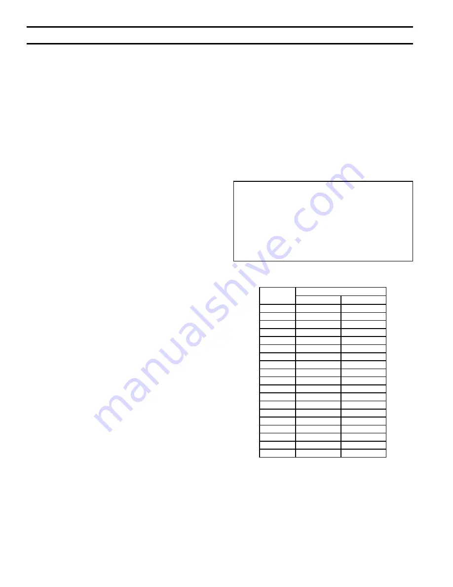
Boiler Size

Water Content (Gallons)

Water Boiler

Steam Boiler

5006B

37.6

25.6

5007B

43.4

29.3

5008B

49.1

33.0

5009B

54.9

36.8

5010B

60.6

40.5

5011B

66.4

44.2

5012B

72.1

47.9

5013B

77.9

51.6

5014B

83.7

55.4

5015B

89.4

59.1

5016B

95.2

62.8

5017B

100.9

66.5

5018B

106.7

70.2

5019B

112.5

73.9

5020B

118.2

77.7

5021B

124.0

81.4

5022B

129.7

85.1

5024B

141.2

92.5

5026B

152.8

100.0

TABle IV:  WATer CONTeNT

SecTiON  iV - OPeRATiON (continued)

Minimum Water Quality Requirements

pH - 8.3 - 10.5
TDS - 3500 ppm
Total alkalinity ppm as CaCO

3

 - 1200

Total copper ppm - .05
Oily matter ppm -1
Total harness ppm -3

same manner as litmus paper, except that it gives 

specific readings.  A color chart on the side of 

the small hydrion dispenser gives the reading in 

pH.  Hydrion paper is inexpensive and obtainable 

from any chemical supply house or through your 

local druggist.  The pH should be in accordance 

to “Minimum Water Quality Requirements” chart 

below.  Add some washout chemicals (caustic soda), 

if necessary, to bring the pH within the specified 

range.  With this lower level of protection, care must 

be exercised to eliminate all of the free oxygen in 

the system.

4.   

Boiler is now ready to be put into service.

Содержание 5006B

Страница 1: ...o b o t s r i a p e r r o e c i v r e s r o F l e b a L g n i t a R n o n w o h s s a r e b m u N l a i r e S d n a r e b m u N l e d o M r e l i o B e d i v o r p r e b m u N l e d o M r e l i o B r...

Страница 2: ...1 2 1 2 3 1 3 3 2 A Draw up Rod Bundle s 3 Sizes One to Three Per Boiler 37 2 2 1 1 49 1 1 1 1 2 2 1 1 1 3 2 67 1 1 1 1 1 1 2 2 2 1 3 A Boiler Assembly Carton s 6 Sizes One to Five Per Boiler 3A6 1 1...

Страница 3: ...1 1 1 1 1 1 1 1 U S A EQUIPMENT CHECK LIST INSPECT SHIPMENT carefully for any signs of damage All equipment is carefully manufactured inspected and packed Our responsibility ceases upon delivery of B...

Страница 4: ...1 2 1 1 2 3 2 1 3 4 3 1 42 1 1 2 1 2 3 1 3 3 2 A Draw up Rod Bundle s 3 Sizes One to Three Per Boiler 37 2 2 1 1 49 1 1 1 1 2 2 1 1 1 3 2 67 1 1 1 1 1 1 2 2 2 1 3 A Boiler Assembly Carton s 6 Sizes On...

Страница 5: ...Nat 120V LP 1 Size One or Two Per Boiler Natural 1 2 Propane 1 1 1 1 1 1 1 1 1 2 2 2 2 2 2 2 2 2 2 U HCP 1 Plain Heater Cover Plate Not furnished on Water Boiler Ordered With Two Tankless Heaters One...

Страница 6: ...5 8 49 1 8 3 3 2 3 1 2 1 2 2 1 1 4 2 12 3445 5019B 104 5 8 12 12 49 27 7 8 49 1 8 49 1 8 3 3 2 3 1 2 1 2 2 1 1 4 2 12 3620 5020B 110 9 9 12 27 1 4 38 27 7 8 54 1 2 49 1 8 3 3 2 3 1 2 1 2 2 1 1 4 2 9 1...

Страница 7: ...ed through openings not furnished with doors are considered a part of the space Volume ft Length ft x Width ft x Height ft b Determine total input of all appliances in the space Add inputs of all appl...

Страница 8: ...assemblies together 15 section larger boilers by first removing upper shipping strip and lower shipping angles from subassemblies Use 4 20 x MS nuts and washers to attach subassemblies see Fig 3 e At...

Страница 9: ...un nut approximately 8 on two 2 draw up rods of equal length Note more than one set of draw up rods are furnished on 8 section and larger boilers Place draw up channel and one flat washer against nut...

Страница 10: ...10 Fig 6 ARRANGEMENT OF SECTIONS AND CANOPY S SECTION III INSTALLATION INSTRUCTIONS continued...

Страница 11: ...lug holes in the front of Boiler and Lower lug holes in the rear of Boiler sections and tighten until they are finger tight only to allow for expansion This is necessary in order to allow clearance fo...

Страница 12: ...st be subjected to a hydrostatic test of 45 psig to 55 psig 2 HOT WATER BOILERS The assembled boiler must be subjected to a hydrostatic test of 75 psig to 85 psig WARNING Failure to properly hydrotest...

Страница 13: ...ith Steam Heating System refer to Fig 12 13 14 or 15 b With Forced Circulation HOT WATER HEATING SYSTEMS see Fig 16A and 16B For additional reference consult I B R Installation and Piping Guide No 250...

Страница 14: ...14 Fig 12 RECOMMENDED STEAM BOILER PIPING GRAVITY RETURN I OR 2 SUPPLY CONNECTIONS 5006B THRU 5014B SECTION III INSTALLATION INSTRUCTIONS continued...

Страница 15: ...15 Fig 13 RECOMMENDED STEAM BOILER PIPING GRAVITY RETURN 3 SUPPLY CONNECTIONS 5015B THRU 5020B SECTION III INSTALLATION INSTRUCTIONS continued...

Страница 16: ...16 Fig 14 RECOMMENDED STEAM BOILER PIPING GRAVITY RETURN 4 OR 5 SUPPLY CONNECTIONS 5021B THRU 5026B SECTION III INSTALLATION INSTRUCTIONS continued...

Страница 17: ...17 Fig 15 Typical Steam Piping Arrangement for Boilers with Pumped Condensate Return and Boiler Feed Unit SECTION III INSTALLATION INSTRUCTIONS continued...

Страница 18: ...BOILER PIPING 1 SUPPLY CONNECTION 1 RETURN CONNECTION SIZES 5006B THRU 5019B Fig 16B RECOMMENDED WATER BOILER PIPING 3 SUPPLY CONNECTIONS 2 RETURN CONNECTIONS SIZES 5020B THRU 5026B SECTION III INSTAL...

Страница 19: ...ng screws see Fig 19 3 See Fig 7 Purpose of Tappings and Their Location and remove necessary knockouts from Upper Left and from Upper Right Jacket End Panels 4 Place Upper Right End Panel on top of Lo...

Страница 20: ...Attach rear top Jacket Panel to Upper End Panels using 8 SMS Refer to Fig 21 20 Installation of Canopy Drafthood 5006B thru 5010B Section Boilers see Fig 22 Place Cerafelt strips on top of section ass...

Страница 21: ...21 Fig 21 EXPLODED VIEW OF JACKET 5006B THRU 5010B SECTION BOILERS SECTION III INSTALLATION INSTRUCTIONS continued...

Страница 22: ...22 Fig 22 SECURING OF CANOPY DRAFTHOOD SECTION III INSTALLATION INSTRUCTIONS continued...

Страница 23: ...23 Fig 23 CANOPY DRAFTHOOD MOUNTING DIAGRAM SECTION III INSTALLATION INSTRUCTIONS continued...

Страница 24: ...24 Fig 24 EXPLODED VIEW OF JACKET 5011B THRU 5019B SECTION BOILERS SECTION III INSTALLATION INSTRUCTIONS continued...

Страница 25: ...to Hex Couplings using 20 x 3 8 slotted pan head machine screws d Attach the Lower Rear Intermediate Panels to the Lower Rear Intermediate Panel Support Bracket s using 10 32 x self tapping screws e A...

Страница 26: ...THRU 5022B SECT BOILERS SECTION III INSTALLATION INSTRUCTIONS continued CAUTION Panel with louvers must be at front of boiler for ventilation of vestibule Panel with perforations must be at front of b...

Страница 27: ...AND 5026B SECT BOILERS SECTION III INSTALLATION INSTRUCTIONS continued CAUTION Panel with louvers must be at front of boiler for ventilation of vestibule Panel with perforations must be at front of bo...

Страница 28: ...extensions d Install Pressure Limit Controls as follows 1 Boiler equipped with 67BC 2 Low Water Cut Off Connect Pressure Limit furnished to street ell and pigtail siphon For installation of second pre...

Страница 29: ...29 Fig 28 MOUNTING ELEVATIONS OF M M 150 AND A 67M FLOAT LWCO SECTION III INSTALLATION INSTRUCTIONS continued...

Страница 30: ...eater Opening Cover Plate d TANKLESS HEATER PERFORMANCE Tankless heater ratings in Series 5B boilers are based on continuous draw temperature rise of 100 F 40 140 F and boiler water temperature of 200...

Страница 31: ...0 1 00 65 96 70 93 36 OPEN GAS TRAIN CARTON S CONNECT GAS TRAIN S TO ELBOW ON END OF MANIFOLD S according to the Gas Trains on pages 86 87 88 89 90 91 or 92 PRESSURE TESTING of gas service piping must...

Страница 32: ...ts of the authority having jurisdiction or in the absence of such requirements to the USA National Fuel Gas Code ANSI Z223 1 CANADA Installation Codes for Natural and LP Gas Burning Appliances and Equ...

Страница 33: ...nnect together and on USA boilers run tubing to bleed line protruding from inside base see Fig 33 On boilers installed in Canada run bleed line to outdoors Fig 32 PILOT PIPING EI CONTROL SYSTEM Robert...

Страница 34: ...uts install the L62GB 3C pilot safety switch bracket on the manifold just to the right of the main burner with pilot Install L62GB 3C pilot safety switch on bracket using two 8 x SMS IN on pilot safet...

Страница 35: ...e front top jacket panel preferably on the closest jacket panel to the gas train installed There are 3 three KO s and 4 four fastener holes provided for this purpose use 4 four 8 SMS to fasten the Con...

Страница 36: ...nd pipe nipple Drill holes in Jacket and fasten Transformer using SMS 2 INSTALLATION OF PILOT PIPING Install the H91WA 4 pilot solenoid valve in the bottom center knockout of the J box using conduit f...

Страница 37: ...e 39 Fig 37 PILOT PIPING EP CONTROL SYSTEM Using OD aluminum tubing connect the pilot shutoff valve installed in the manual shutoff valve in the gas train to the inlet of the RV 12LT regulator packed...

Страница 38: ...and nuts Mount junction box to bracket using 8 SMS see Figures 38 and 39 Install Transformer on junction box THERMOCOUPLE CONTROL SYSTEM CANADA ONLY Fig 38 PILOT PIPING THERMOCOUPLE CONTROL SYSTEM CAN...

Страница 39: ...M86 and local codes for venting SOME ITEMS RELATIVE TO CONSTRUCTION AND SIZING OF VENT SYSTEM 1 Total Vent Height 2 Vent Connector make Initial Rise as high as possible 3 Length of Lateral hold to a...

Страница 40: ...ed to the common venting system Turn on any exhaust fans such as range hoods and bathroom exhausts so they will operate at maximum speed Do not operate a summer exhaust fan Close fireplace dampers d P...

Страница 41: ...boiling and trickle of overflow for several hours until the water coming from the overflow is clear d Stop burner and drain boiler in a manner and to a location that hot water can be discharged with...

Страница 42: ...in return main turn on burner and allow condensate to flow to drain until it has run clear for at least 30 minutes while feeding water to boiler so as to maintain normal water level Turn off burner d...

Страница 43: ...VALVES REFERENCE PAGE PILOT MAIN 5006B 5009B USA EI Elec Ign 1 7000DERHC S7C 45 5006B 5026B USA OP Standing Q179D 1 L62GB 3C 2 V88A A 51 53 5006B 5026B CANADA OP Standing Q179D 1 L62GB 3C 2 V88A 51 53...

Страница 44: ...ion Controls is interrupted thus de energizing terminals PV and MV Loss of power to these terminals means loss of power to all pilot gas valves and to main gas valves respectively Thus pilot burner an...

Страница 45: ...45 Fig 42 SCHEMATIC WIRING DIAGRAM EI CONTROL SYSTEM ROBERTSHAW7000 GAS VALVE U S A 5006B THRU 5009B SECTION IV OPERATION continued...

Страница 46: ...main gas valves starting main burner operation When the operating control is satisfied the pilot gas valve and the main gas valves are de energized stopping the burner operation In the event of excess...

Страница 47: ...47 Fig 44 SCHEMATIC wiring diagram 5015B THRU 5026B SECTION BOILERS EI CONTROL SYSTEM SECTION IV OPERATION continued...

Страница 48: ...nt of excessive steam pressure steam boiler or excessive water temperature water boiler the high limit control will de energize the pilot valves and main gas valves on both sides stopping burner opera...

Страница 49: ...49 TROUBLE SHOOTING GUIDE BOILERS EQUIPPED WITH S8610M INTERMITTENT ELECTRIC IGNITION SECTION IV OPERATION continued...

Страница 50: ...e lighted by pilot 6 When operating control is satisfied terminals 6 and 9 are de energized Main Gas Valves close and main burners are extinguished 7 The pilot continues to burn c SAFETY SHUTDOWN 1 SA...

Страница 51: ...51 Fig 46 wiring diagram 5006B THRU 5014B SECTION BOILERS OP CONTROL SYSTEM SECTION IV OPERATION continued...

Страница 52: ...rol is energized 2 A component check circuit in each RM7890C is activated which checks the electronic network of the relay 3 Flame rod circuit between each Q179D pilot and terminal 11 on its respectiv...

Страница 53: ...53 Fig 47 wiring diagram 5015B THRU 5026B SECION BOILERS OP CONTROL SYSTEM SECTION IV OPERATION continued...

Страница 54: ...gas to pilot Terminal 10 energizes ignition transformer creating electric spark ignition at pilot 4 Flame rod circuit between Q179C pilot and RM7890A proves presence of pilot flame electronically 5 T...

Страница 55: ...55 Fig 48 wiring diagram 5006B THRU 5014B SECTion BOILERS EP CONTROL SYSTEM SECTION IV OPERATION continued...

Страница 56: ...56 Fig 49 wiring diagram 5015B THRU 5026B SECTION BOILERS EP CONTROL SYSTEM SECTION IV OPERATION continued...

Страница 57: ...and thus 100 shut off is achieved a OPERATING INSTRUCTIONS 1 MakesureallManualMainShut offValvesand all Pilot Valves have been off for at least five minutes 2 Set Operating and Limit Controls to desir...

Страница 58: ...Canada Only The 5006B thru 5013B boilers are equipped with a Thermocouple Control System that utilizes a constant burning Q327A pilot a Q309 thermocouple and a L62GB 3C Pilot Safety Switch The Q309 t...

Страница 59: ...ve boiler water temperature water boiler Low water cut off D will stop burner operation if the water level in boiler drops below the lowest safe level The pilot safety switch E connected to main gas v...

Страница 60: ...oiler The low water cut off D will stop burner operation if the water level in the boiler drops below the low est safe level Should one of the pilot flames become extinguished the pilot safety switch...

Страница 61: ...rger Reinstall and recheck input rate b Additional Check on Input Since input is a function of heating value specific gravity and volume of gas flow contact your utility for the first two items in ord...

Страница 62: ...ustment is preset at the factory in the MAX position Fig 53 shows the Limit Switch Cam and Scales to indicate direction to rotate cam for increasing or decreasing low fire input on the Honeywell V4062...

Страница 63: ...eral times to be sure the low fire setting is that desired and suitable for correct burner light off 7 Turn off power supply Remove R W jumper and reconnect the lead to terminal R on the V9055A 8 Repl...

Страница 64: ...the module c OP and EP Pilot Systems Carefully remove the flame rod wire from terminal 11 on the RM7890 Control Main gas and pilot gas must shut off If not replace the RM7890 Control 21 COMBUSTION CH...

Страница 65: ...NT PANEL DANGER This boiler used flammable gas high voltage electricity moving parts and very hot water under high pressure Assure that all gas and electric power supplies are off and that the water t...

Страница 66: ...Long sleeved loose fitting clothing 3 Gloves 4 Eye Protection Take steps to assure adequate ventilation Wash all exposed body areas gently with soap and water after contact Wash work clothes separatel...

Страница 67: ...necessary to remove the rear cleanout panels Remove the Burner Access Panels at front of base and place paper or cardboard over burners With long handle wire flue brush and vacuum brush flueways thoro...

Страница 68: ...68 Fig 58 PILOT LOCATIONS SECTION V SERVICE continued...

Страница 69: ...all parts installed on the boiler that require lubrication Generally this involves only the circulator in a hot water system This includes a Type of lubricant to be used b Frequency of lubrication c P...

Страница 70: ...tion to solder joints on bellows and float when this type of control is used Check float for evidence of collapse and check mercury bulb where applicable for mercury separation or discoloration Do not...

Страница 71: ...t and the oxygen escapes as a gas Both can result in reduced boiler life The accumulation of sediment can eventually isolate the water from contacting the cast iron When this happens the cast iron in...

Страница 72: ...72 SERVICE RECORD DATE SERVICE PERFORMED...

Страница 73: ...olenoid Valves Pilot Line Regulators EP OP Control Panel 101 Pilot Assemblies 102 thru 104 All Series 5B Repair Parts may be obtained through your local Burnham Wholesale distributor Should you requir...

Страница 74: ...74 Fig 64 BASE PARTS 5006B Thru 5014B SECTION VI REPAIR PARTS continued...

Страница 75: ...3095 Base Rear Panel Insulation 1 Supertemp 8 3 4 x 21 5 8 11 2 pcs 72013105 Base Rear Panel Insulation 1 Supertemp 8 3 4 x 24 5 16 11 2 pcs 72013115 Base Rear Panel Insulation 1 Supertemp 8 3 4 x 29...

Страница 76: ...76 Fig 65 BASE PARTS 5015B thru 5026B SECTION VI REPAIR PARTS continued...

Страница 77: ...24 5 16 11 2 pcs 11 2 pcs 11 2 pcs 11 2 pcs 11 2 pcs 72013115 Base Rear Panel Insulation 1 Thick 8 3 4 x 29 3 4 11 2 pcs 11 2 pcs 72013125 Base Rear Panel Insulation 1 Thick 8 3 4 x 35 3 16 11 2 pcs 7...

Страница 78: ...78 Fig 66 INTEGRAL CANOPY DRAFTHOODS SECTIONS SECTION VI REPAIR PARTS continued...

Страница 79: ...1 2 X 31 3 16 61113073 5007B 2 1 2 1 36 1 2 X 36 5 8 61113083 5008B 3 1 2 36 1 2 X 41 1 16 61113093 5009B 4 36 1 2 X 47 1 2 61113103 5010B 5 5016B 5017B 5018B 5019B 5020B 36 1 2 X 25 3 4 61113063 500...

Страница 80: ...er Section Plain 4 5 6 7 8 8 9 10 11 12 13 14 15 16 16 17 18 19 21 7171302 REH Section 1 1 1 1 1 1 1 1 1 1 1 1 1 1 1 1 1 1 1 7171304 CX Center Section Tapped Not Plugged 1 1 1 1 1 1 2 2 3 3 6171301 CX...

Страница 81: ...18131071 618131071 618131071 618131371 618131371 Right Base Subass y w OP Pilot Ass y 61813088 61813098 61813098 61813108 61813108 61813108 61813108 61813108 61813138 61813138 Right Base Subass y w EP...

Страница 82: ...82 Fig 67 JACKETS SECTION VI REPAIR PARTS continued...

Страница 83: ...x 42 5 8 23 60413092 5009B Upper Rear Panel 24 1 2 x 48 1 16 23 60413102 5010B Upper Rear Panel 24 1 2 x 53 1 2 23 60413053 5005B Lower Rear Panel 9 1 2 x 26 5 16 27 28 27 60413063 5006B Lower Rear Pa...

Страница 84: ...8 604130910 5009B Vestibule Panel 25 x 50 1 4 18 604131010 5010B Vestibule Panel 25 x 55 11 16 18 604130511 5005B Rear Top Panel 3 3 4 x 28 5 8 5 6 5 604130611 5006B Rear Top Panel 3 3 4 x 34 1 16 5 6...

Страница 85: ...413082 5008B Upper Rear Panel 24 1 2 x 42 5 8 24 23 24 23 23 60413092 5009B Upper Rear Panel 24 1 2 x 48 1 16 24 23 24 25 25 25 60413043 5004B Lower Rear Panel 9 1 2 x 20 7 8 5 28 60413053 5005B Lower...

Страница 86: ...p Panel 3 3 4 x 44 15 16 6 5 6 5 604130911 5009B Rear Top Panel 3 3 4 x 50 3 8 6 5 6 7 7 7 604131011 5010B Rear Top Panel 3 3 4 x 55 13 16 6041331 Intermediate Vestibule Panel 6 1 8 x 24 22 22 22 22 2...

Страница 87: ...0003 Nipple 1 x 2 1 806600004 Nipple 1 1 2 x 3 1 1 1 806600006 Bushing Hex 1 1 2 x 3 4 1 1 1 806600507 Elbow Reducing 1 1 2 x 3 4 x 90 1 1 806601506 Elbow Reducing 1 1 2 x 1 x 90 1 806601507 Relief Va...

Страница 88: ...onBraCo 13 202 08 1 x 1 15 psi 1 81660501 Safety Valve ConBraCo 13 213 08 1 x 1 15 psi 1 81660505 Safety Valve Conbraco 13 214 08 1 x 2 15 psi 1 81660503 Miscellaneous Fittings Coupling Reducing x Mou...

Страница 89: ...SIZE 5006B 5007B 5008B 5009B 81660151 Robertshaw 7000DERHC S7C 1 x 1 Gas Valve Nat 1 1 1 1 OR 81660158 Robertshaw 7000DERHC LP S7C 1 x 1 Gas Valve LP 1 1 1 1 806604002 1 Ground Joint Union 2 2 2 2 80...

Страница 90: ...0 x 6 0 WC 8226006 Maxitrol RV 61 1 x 1 3A 3A 3A 822607 Maxitrol RV 81 1 x 1 3A 3A 3A LP Gas Regulator HO1 Blue Spring 5 5 to 12 0 WC 8226011 Maxitrol RV 61 1 x 1 3B 3B 3B 8226012 Maxitrol RV 81 1 x...

Страница 91: ...lator Std Cad Plate Spring 3 0 x 6 0 WC 8226006 Maxitrol RV 61 1 x 1 3 3 3 822607 Maxitrol RV 81 1 x 1 3 3 3 822614 Leak Limiter Maxitrol 12A04 incl w RV 61 4 4 4 8226010 Leak Limiter Maxitrol 12A34 i...

Страница 92: ...ywell V9055A1055 5026B Sec Opening Time 120V 60HZ Solenoid Gas Valve 81660088 1 ITT Gen K3A562 3 3 3 81660086 1 ITT Gen K3A772 3 3 3 Nat Gas Regulator Std Cad Plate Spring 3 0 x 6 0 WC 8226006 Maxitro...

Страница 93: ...Valve 81660149 1 Honeywell V8944B1019 1 1 1 81660150 1 Honeywell V8944B1027 1 1 1 Solenoid Gas Valve 81660081 1 ITT Gen K8A461 3 3 3 81660094 1 ITT Gen K8A771 3 3 3 Manual Shutoff Valve 822615 ConBraC...

Страница 94: ...x 6 0 WC 8226006 Maxitrol RV 61 1 x 1 3 3 3 8226012 Maxitrol RV 81 1 x 1 3 3 3 LP Gas Regulator HO1 Blue Spring 5 5 to 12 0 WC 8226011 Maxitrol RV 61 1 x 1 3 3 3 8226012 Maxitrol RV 81 1 x 1 3 3 3 Lea...

Страница 95: ...lve 81660088 1 ITT Gen K3A562 3 3 3 81660094 1 ITT Gen K3A772 3 3 3 Nat Gas Regulator Std Cad Plate Spring 3 0 x 6 0 WC 8226006 Maxitrol RV 61 1 x 1 4A 4A 4A 822607 Maxitrol RV 81 1 x 1 4A 4A 4A LP Ga...

Страница 96: ...RT NO 6011301 100958 01 Description Manifold Module Support Bracket Assembly Honeywell S8610M3009 Ignition Module IGNITION MODULE S8610M SUPPORT BRACKET EI CONTROL SYSTEM SECTION VI REPAIR PARTS conti...

Страница 97: ...STAT L62GB SUPPORT BRACKET OP THERMOCOUPLE CONTROL SYSTEM SECTION VI REPAIR PARTS continued ITEM 1 2 PART NO 6011301 80160138 Description Manifold Module Support Bracket Assembly L62GB 3C Pilot Safety...

Страница 98: ...136001 1 J Box Mounting Bracket 24V 100 VA Transformer 120 60HZ Primary 80160016 2 Penn Y64T22 0 Plate Mounted 822666 3 Penn Pilot Solenoid Valve H91WG 6 8226005 Pilot Line Regulator Nat Gas Maxitrol...

Страница 99: ...ontrol Mounting Bracket 24V 40 VA Transformer 120V 60HZ Primary 80160039 2A USA Honeywell Plate Mounted AT140D1012 80160014 2B Canada Honeywell Foot Mounted AT72D1089 8226005 3 Pilot Line Regulator Na...

Страница 100: ...6001 1 J Box Mounting Bracket 24V 40 VA Transformer 120 60HZ Primary 80160039 2A USA Honeywell Plate Mounted AT140D1012 80160014 2B Canada Honeywell Foot Mounted AT72D1089 8226005 3 Pilot Line Regulat...

Страница 101: ...24V 40 VA Transformer 120V 60HZ Primary 80160039 2A USA Honeywell Plate Mounted AT140D1012 80160014 2B Canada Honeywell Foot Mounted AT72D1089 822662 3 Penn Pilot Solenoid Valve H91WA 4 120V 8226005 4...

Страница 102: ...102 Control assembly and mounting bracket OP EP CONTROL SYSTEMS SECTION VI REPAIR PARTS continued...

Страница 103: ...332 01 1 Pilot Burner Igniter Sensor Honeywell Q3481B1180 LP Gas with KR14 orifice 6136054 2 Pilot Ground Wire Assembly 36 5006B 5009B 6137375 2 Pilot Ground Wire Assembly 72 5010B 5026B 8236015 3 Ven...

Страница 104: ...e LP Honeywell Q179D1008 w 388146 KD Orifice 8236004 2 Thermocouple Honeywell Q309A1996 36 Long 7136256 3 Flame Rod Lead Honeywell R1298020 6 Long 8236021 4 Female Rajah Connector Honeywell 37356 6236...

Страница 105: ...09 w 388146 AG Orifice 7136255 2 Ignition Lead Honeywell R1061012 6 Long 7136256 3 Flame Rod Lead Honeywell R1298020 6 Long 8236021 4 Female Rajah Connector Honeywell 37356 6236020 5 Ground Wire Conti...

Страница 106: ...Boiler Piping 1 Supply Connection and 1 Return Connection Sizes 5006B Thru 5019B Section Boilers Fig 16B 18 Recommended Water Boiler Piping 3 Supply Connections and Two Return Connections Sizes 5020B...

Страница 107: ...ol System Canada Only Fig 51 60 Wiring Diagram 5015B Thru 5024B Section Boilers Thermocouple Control System Canada Only Fig 52 62 V8944B Combination Valve Fig 53 63 Low Fire Adjustment V4062 Actuator...

Страница 108: ...99 Transformer and Pilot Line Regulator OP Control System Maxitrol Pilot Reg Ass y 100 Transformer and Pilot Line Regulator Thermocouple Control System Canada Penn Pilot Solenoid Valve Ass y 101 Trans...

Страница 109: ...B Table 2B 77 Series 5B Base Parts 5015B Thru 5026B Table 3A 79 Series 5B Integral Canopy Drafthoods Boiler Sizes 5006B Thru 5010B Table 3B 80 Series 5B Section Replacement Chart Table 3C 81 Series 5B...

Страница 110: ...nn H91WA 4 Pilot Solenoid Valve and Pilot Line Regulator EP Control System Honeywell Q3481 Pilot Ass y 103 EI Control System Honeywell Q3481 Pilot Assembly Honeywell Q179D Pilot Ass y 104 OP Control S...

Страница 111: ...111 SERVICE RECORD DATE SERVICE PERFORMED...

Страница 112: ...112...

Отзывы: