Bryant CONDENSING GAS FURNACE 352MAV Скачать руководство пользователя страница 4

Always install furnace to operate within the furnace’s intended
rise range with a duct system which has an external static
pressure within the allowable range, as specified in the SET
TEMPERATURE RISE section of these instructions.

When a furnace is installed so that supply ducts carry air
circulated by the furnace to areas outside the space containing
the furnace, the return air shall also be handled by duct(s)
sealed to the furnace casing and terminating outside the space
containing the furnace.

A gas-fired furnace for installation in a residential garage must
be installed as specified in the Hazardous Locations section of
these instructions.

The furnace is not to be used for temporary heating of buildings
or structures under construction unless the furnace installation
and operation complies with the first CAUTION in the LOCA-
TION section of these instructions.

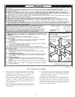
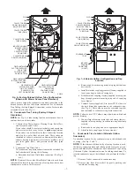
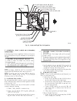
This furnace must be installed with a direct-vent (combustion air
and flue gas) system and a factory accessory termination kit. In a
direct-vent system, all air for combustion is taken directly from the
outdoor atmosphere and flue gases are discharged to the outdoor
atmosphere. See furnace and factory accessory termination kit
instructions for proper installation.

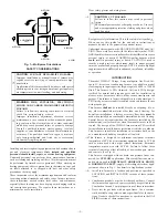
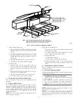
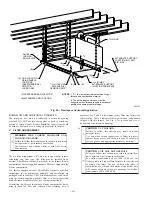
Fig. 3—Clearances to Combustibles

A04110

This forced air furnace is equipped for use with natural gas at altitudes 0 - 10,000 ft (0 - 3,050m), except 140 size furnaces are only approved for altitudes 0 - 7,000 ft.
(0 - 2,135m).
An accessory kit, supplied by the manufacturer, shall be used to convert to propane gas use or may be required for some natural gas applications.
This furnace is for indoor installation in a building constructed on site.  This furnace may be installed in a manufactured (mobile) home when stated on rating plate and
using factory authorized kit..
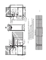
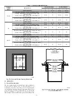
This furnace may be installed on combustible flooring in alcove or closet at 

Minimum Inches Clearance To Combustible Construction

 as described below.

This furnace requires a special venting system.  Refer to the installation instructions for parts list and method of installation. This furnace is for use with schedule-40 PVC,
PVC-DWV, CPVC, or ABS-DWV pipe, and must not be vented in common with other gas-fired appliances. Construction through which vent/air intake pipes may be
installed is maximum 24 inches (600 mm), minimum 3/4 inches (19 mm) thickness (including roofing materials).

MINIMUM INCHES CLEARANCE TO COMBUSTIBLE CONSTRUCTION

*

Minimum front clearance for service 24 inches (610mm).
140 size furnaces require 1 inch back clearance to combustible materials.

For installation on combustible floors only when installed on special base No. KGASB0201ALL,
Coil Assembly, Part No. CD5 or CK5, or Coil Casing, Part No. KCAKC.

Line contact is permissible only between lines formed by intersections of top and two sides of
furnace jacket, and building joists, studs, or framing.
Clearance shown is for air inlet and air outlet ends.
120 and 140 size furnaces require 1 inch bottom clearance to combustible materials.

Ø

Clearance in inches
Dégagement (po).

Vent clearance to
  combustibles 0".

0 (po) Dégagement
 

d´évent avec combustibles.

Dégagement avant minimum de 610mm (24 po) pour l

´

entretien.

Pour les fournaises de 140 taille, 1 po (25mm) dégagement des matériaux combustibles est
requis au-arriere.

This furnace is approved for UPFLOW, DOWNFLOW and
HORIZONTAL installations.

Cette fournaise est approuvée pour l´installation HORIZONTALE
et la circulation d´air VERS LE HAUT et VERS LE BAS.


*

BOTTOM

DESSOUS

0"

Ø

3"

0"

§

0"

TO

P

/P

LE

N

U

M

DE

S

S

US

/C

H

A

M

B

RE

 D´

A

IR

1"

0"

§

24

MIN

ALL POSITIONS:

DOWNFLOW POSITIONS:

I

HORIZONTAL POSITIONS:

:

S I

D E

C

O T

E S

F

R

O

N

T

A

V

A

N

T

B

C

K

A

R

R I

E

A

E

R

S

E

R V

I

E

C

L È

NT

R

T

E

N

E

I

V

A

N

A

T

F R

ON

T

S I

D E

C

O T

E

S

F O

U

U

F

R N

A C

S

E

E

I

A

R N

Les fléches de dégagement 

ne change pas avec  

l´orientation de la  

générateur d´air chaud.

Clearance arrows
do not change with
furnace orientation.

††

UPFLOW OR
DOWNFLOW

FRONT

FRONT

LEVEL (0") TO

1/2" MAX

† †

INSTALLATION

POUR LA POSITION HORIZONTALE:

POUR LA POSITION COURANT DESCENDANT:

POUR TOUS LES POSITIONS:

U

Ø

*

§

§

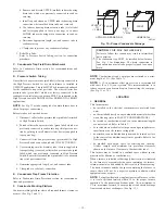
For upflow and downflow applications, furnace must be installed level, or pitched within 1/2" of level. For a
horizontal application, the furnace must be pitched minimum 1/4" to maximum of 1/2" forward for proper
drainage.  See Installation Manual for IMPORTANT unit support details on horizontal applications.

HORIZONTAL


DÉGAGEMENT MINIMUM EN POUCES AVEC ÉLÉMENTS DE CONSTRUCTION COMBUSTIBLES


† †

Pour l

´

installation sur le plancher combustible seulement quand on utilise la base spéciale, pièce

nº KGASB0201ALL, l

´

ensemble serpentin, pièce nº CD5 ou CK5, ou le carter de serpentin,

pièce nº  KCAKC.

Le contact n

´

est permis qúentre les lignes formées par les intersections du dessus et des

deuxcôtés de la chemise de la fournaise, et des solives, des montants ou de la charpente du
bátiment.
La distance indiquée concerne l

´

extrémité du tuyau d

´

arrivée d

´

air et l

´

extrémité du tuyau de sortie

d

´

air.

Pour les fournaises de 120 et 140 taille, 1 po (25mm) dégagement des matériaux combusitbles
est requis au-dessous.


MIN 1/4" TO 1/2" MAX

Cette fournaise à air pulsé est équipée pour utilisation avec gaz naturel et altitudes comprises entre 0 - 3,050m (0 - 10,000 pi),excepté queles fournaises de 140 taille
sont pour altitudes comprises entre 0 - 2,135m (0 - 7,000pi).
Utiliser une trousse de conversion, fournie par le fabricant, pour passer au gaz propane ou pour certaines installations au gaz naturel.
Cette fournaise à air pulsé est pour installation à l´intérieur dans un bâtiment construit sur place.  Cette fournaise à air pulse peut être installée dans une maison
préfabriquée (maison mobile) si prescrit par la plaque signalétique et si l' on utilise une trousse specifiée par le fabricant.
Cette fournaise peut être installée sur un plancher combustible dans un enfoncement ou un placard en observant les 

Dégagement Minimum En Pouces Avec

Éléments De Construction Combustibles.

Cette fournaise nécessite un système d´évacuation spécial. La méthode d´installation et la liste des pièces nécessaires figurent dans les instructions d´installation.  Cette
fournaise doit s´utiliser avec la tuyauterie des nomenclatures 40 PVC, PVC-DWV, CPVC, ou  ABS-DWV et elle ne peut pas être ventilée conjointment avec d´autres
appareils à gaz. Épaisseur de la construction au travers de laquelle il est possible de faire passer les tuyaux d'aération (admission/évacuation): 24 po (600 mm)
maximum, 3/4 po (19mm) minimum (y compris la toiture).

Pour des applications de flux ascendant et descendant, la fournaise doit être installée de niveau ou inclinée à
pas plus de 1/2" du niveau.  Pour une application horizontale, la fournaise doit être inclinée entre minimum
1/4" et maximum 1/2" du niveau pour le drainage approprié.  En cas d´installation en position horizontale,
consulter les renseignements IMPORTANTS sur le support dans le manuel d´installation.

328066-201 REV. B  LIT TOP

—4—

Содержание CONDENSING GAS FURNACE 352MAV

Страница 1: ...nnections 17 Filter Arrangement 18 Bottom Closure Panel 19 Gas Piping 19 Electrical Connections 20 115 V Wiring 20 24 V Wiring 21 Accessories 22 Direct Venting 22 Removal of Existing Furnaces from Com...

Страница 2: ...s which could result in personal injury or death CAUTION is used to identify unsafe practices which may result in minor personal injury or product and property damage NOTE is used to highlight suggest...

Страница 3: ...n air openings for airflow requirements above 1800 CFM at 0 5 W C ESP 17 5 16 24 1 2 27 9 16 TYP 27 5 8 29 11 16 TYP 30 13 16 32 5 8 TYP 33 1 4 TYP CONDENSATE DRAIN TRAP LOCATION ALTERNATE UPFLOW 7 8...

Страница 4: ...LOW and HORIZONTAL installations Cette fournaise est approuv e pour l installation HORIZONTALE et la circulation d air VERS LE HAUT et VERS LE BAS BOTTOM DESSOUS 0 3 0 0 TOP PLENUM DESSUS CHAMBRE D AI...

Страница 5: ...Engineers ASHRAE 2001 Fundamentals Handbook Chapter 34 V ACOUSTICAL LINING AND FIBROUS GLASS DUCT US and CANADA current edition of SMACNA NFPA 90B as tested by UL Standard 181 for Class I Rigid Air Du...

Страница 6: ...attic application or over a finished ceiling NOTE In Canada installations shall be in accordance with current NSCNGPIC and or local codes I GENERAL Some assembly and modifications are required for fur...

Страница 7: ...e Fig 6 These elbows must be cemented together and cemented to condensate trap drain connection NOTE Failure to use CPVC elbows may allow drain to kink and prevent draining f Connect larger diameter d...

Страница 8: ...priate length cut and connect tube E Condensate Trap Field Drain Attachment Refer to Condensate Drain section for recommendations and procedures F Pressure Switch Tubing The LOWER collector box pressu...

Страница 9: ...r box drain to condensate trap as shown in Fig 9 d Determine appropriate length and cut e Connect to condensate trap f Clamp tube to prevent any condensate leakage 2 Inducer Housing Drain Tube a Remov...

Страница 10: ...bustion products being drawn in from appliances in the equipment room 4 Install condensate trap into left hand side casing hole by inserting tube connection stubs through casing hole and rotating unt...

Страница 11: ...bel attached to High Pressure Switch 2 Use smaller diameter tube factory supplied in loose parts bag to extend tube disconnected in item 1 3 Route extended tube a Behind inducer housing b Between blow...

Страница 12: ...o follow this warning could result in personal injury or death Casing hole filler cap must be installed in blower shelf hole when condensate trap is relocated to prevent com bustion products being dra...

Страница 13: ...r recommenda tions and procedures F Construct a Working Platform Construct working platform where all required furnace clearances are met See Fig 3 and 11 CAUTION UNIT MAY NOT OPERATE Failure to follo...

Страница 14: ...rature of the return air to the furnace is maintained between 55 F 13 C and 80 F 27 C with no evening setback or shutdown The use of the furnace while the structure is under construction is deemed to...

Страница 15: ...n Table 1 and Fig 18 3 Construct plenum to dimensions specified in Table 1 and Fig 18 4 If downflow subbase KGASB is used install as shown in Fig 19 If Coil Assembly Part No CD5 or CK5 or Coil Box Par...

Страница 16: ...C Coil Box 15 1 2 19 16 1 2 20 21 Upflow Applications 19 1 2 24 1 8 20 1 8 24 3 4 Downflow Applications on Non Combustible Flooring 19 3 8 19 20 19 5 8 Downflow Applications on Combustible Flooring Us...

Страница 17: ...ain casing DOWNFLOW FURNACES Connect supply air duct to supply air opening on furnace The supply air duct attachment must ONLY be connected to furnace supply outlet or air conditioning coil casing whe...

Страница 18: ...ble 2 to determine correct filter size for desired filter location Table 2 indicates filter size location and quantity shipped with this furnace See Fig 2 for location and size of bottom and side retu...

Страница 19: ...for gas leaks with an open flame Use a commercially available soap solution made specifically for the detection of leaks to check all connections Use proper length of pipe to avoid stress on gas cont...

Страница 20: ...een yellow wire routed to gas valve C terminal and burner box screw A 115 V Wiring Before proceeding with electrical connections make certain that voltage frequency and phase correspond to that specif...

Страница 21: ...se ONLY a 3 amp fuse of identical size type The control will flash code 24 when fuse needs replacement Fig 27 Heating and Cooling Application Wiring Diagram 1 Stage Thermostat and Condensing Unit A990...

Страница 22: ...hall be installed in accordance to these instructions A Removal of Existing Furnaces from Common Vent Systems When an existing Category I furnace is removed or replaced the original venting system may...

Страница 23: ...EMITTING DIODE FOR STATUS CODES AMBER LGPS LOW GAS PRESSURE SWITCH SPST N O LPS LOW HEAT PRESSURE SWITCH SPST N O LS LIMIT SWITCH AUTO RESET SPST N C OL AUTO RESET INTERNAL MOTOR OVERLOAD TEMPERATURE...

Страница 24: ...P SEC 1 SEC 2 PL1 NEUTRAL L2 1 EAC 2 BHT CLR BHI LOR PL3 1 BLWR COOL SPARE 1 SPARE 2 1 AMP 115 VAC EAC 1 PR 1 IDR HSIR IDM IHI LOR PL2 1 HSI HI LO STAT U S C O D E L E D HI HEAT LO HEAT L1 TABLE 5 APP...

Страница 25: ...Standards Institute ANSI stan dards and American Society for Testing and Materials ASTM standards See Table 5 for approved materials for use in the U S A See Table 7 for maximum pipe lengths and Fig 3...

Страница 26: ...erline extended above or below vent terminal of the furnace to a dryer or water heater vent or other appliance s direct vent intake or exhaust 12 30 cm 12 30 cm O Clearance from a plumbing vent stack...

Страница 27: ...use this diameter for both combustion air and vent pipes 2 When installing vent systems of short pipe length use the smallest allowable pipe diameter Do not use pipe size greater than required or inco...

Страница 28: ...move pipe for service of igniter or flame sensor COMBUSTION AIR INTAKE HOUSING PLUG FITTING The combustion air intake plug fitting must be installed in unused combustion air intake housing This fittin...

Страница 29: ...st vent condensate disposal When this vent extension pipe is supplied it must be used to connect the field vent pipe to furnace inducer housing on ALL upflow and downflow applications NOTE See label o...

Страница 30: ...2 in 2 in and 2 1 2 in diameter pipe systems when single penetration of wall or roof is desired 4 The 3 in concentric vent air termination kit is for 2 1 2 in 3 in and 4 in diameter pipe systems when...

Страница 31: ...IMUM ALLOWABLE PIPE LENGTH FT CONTINUED ALTITUDE FT UNIT SIZE TERMINATION TYPE PIPE DIA IN NUMBER OF 90 ELBOWS 1 2 3 4 5 6 8001 to 9000 036060 2 Pipe or 2 in Concentric 1 1 2 11 6 NA NA NA NA 2 49 44...

Страница 32: ...AIN 12 IN CLEARANCE ABOVE HIGHEST ANTICIPATED SNOW LEVEL OR GRADE WHICHEVER IS GREATER 90 VENT 12 IN SEPARATION BETWEEN BOTTOM OF COMBUSTION AIR AND BOTTOM OF VENT BRACKET COUPLING 12 MINIMUM OVERHANG...

Страница 33: ...be damaged by or subjected to foreign objects such as stones balls etc e Termination kit should be positioned where vent vapors are not objectionable 2 Cut one 4 in diameter hole for 2 in kit or one 5...

Страница 34: ...uld be taken when freezing ambient may freeze drain pipe and prohibit draining WARNING PERSONAL INJURY HAZARD Failure to follow this warning could result in property damage and personal injury or deat...

Страница 35: ...m Separation A93056 COMBUSTION AIR VENT VENT A Fig 47 Sidewall Termination of More Than 12 in Dimension A is Touching or 2 In Maximum Separation A96130 COMBUSTION AIR COMBUSTION AIR VENT A Fig 45 Conc...

Страница 36: ...inducer housing drain connection 3 Insert field supplied funnel into tube 4 Pour 1 quart of water into funnel tube Water should run through inducer housing overfill condensate trap and flow into open...

Страница 37: ...ting mode when OFF in response to a call for heat See Fig 32 This furnace can operate as a 2 stage furnace with a single stage thermostat because furnace control CPU includes a programmed adaptive seq...

Страница 38: ...h Single Speed Air Conditioner Fig 52B Two Stage Furnace with Two Speed Air Conditioner A00276 A00277 Fig 52C Two Stage Furnace with Single Speed Heat Pump Dual Fuel A00278 Fig 52D Two Stage Furnace w...

Страница 39: ...Heat Pump A00281 Fig 52G Two Stage Thermostat With Two Stage Furnace and Two Speed Air Conditioner A00280 Fig 52F Dual Fuel Thermostat With Two Stage Furnace and Two Speed Heat Pump A00282 Fig 52H Sin...

Страница 40: ...pplications 10 NO connection should be made to the furnace HUM terminal when using a Thermidistat 11 Optional connection If wire is connected dip switch No 1 on furnace control should be set in ON pos...

Страница 41: ...3 7 1 6 45 3 8 1 6 44 3 2 1 4 44 3 4 1 4 44 3 5 1 5 1025 45 3 5 1 5 45 3 6 1 5 45 3 7 1 6 44 3 2 1 3 44 3 3 1 4 1050 45 3 3 1 4 45 3 4 1 5 45 3 6 1 5 45 3 7 1 6 45 3 8 1 6 1075 45 3 2 1 3 45 3 3 1 4 4...

Страница 42: ...4 44 3 4 1 4 44 3 5 1 5 875 45 3 3 1 4 45 3 6 1 5 45 3 7 1 6 44 3 2 1 3 44 3 3 1 4 900 45 3 3 1 4 45 3 4 1 4 45 3 5 1 5 45 3 6 1 5 45 3 8 1 6 925 47 3 7 1 6 45 3 2 1 4 45 3 3 1 4 45 3 4 1 5 45 3 6 1 5...

Страница 43: ...no Manifold Pressure Orifice no Manifold Pressure Orifice no Manifold Pressure Orifice no Manifold Pressure U S A Only 7001 to 8000 15 derate 625 43 3 8 1 6 42 3 3 1 4 42 3 4 1 4 42 3 5 1 5 42 3 6 1 5...

Страница 44: ...cooling as long as the thermostat continues to call for cooling Subsequent selection is based on stored history of the thermostat cycle times The wall thermostat calls for cooling closing the R to G a...

Страница 45: ...shut off for 24 seconds then come back on at LO HEAT speed When the W W1 input signal disappears the furnace control begins a normal inducer post purge period and the blower remains running at LO HEA...

Страница 46: ...urner enclosure front REMOVED b Remove regulator seal caps that conceal adjustment screws for low and high heat gas valve pressure regula tors See Fig 53 c Move setup switch SW 1 on control center to...

Страница 47: ...in low heat operation h Jumper R to W W1 i Let furnace run for 3 minutes in low heat operation j Measure time in sec for gas meter to complete 1 revolution Note reading k Refer to Table 11 for cubic f...

Страница 48: ...SHOCK HAZARD Failure to follow this warning could result in personal injury or death Disconnect 115 v electrical power before changing speed tap To change blower motor speed selections for heating mod...

Страница 49: ...blocked to permit normal air circulation By using this method to check limit control it can be established that limit is functioning properly and operates if there is a restricted return air duct or m...

Страница 50: ...e Sloped To Furnace Pipe Insulation ________ Over Ceilings ________ Low Ambient Exposed Pipes Condensate Drain ________ Unit Level or Pitched Forward ________ Internal Tubing Connections Free of Kinks...

Страница 51: ...51...

Страница 52: ...2005 Bryant Heating Cooling Systems 7310 W Morris St Indianapolis IN 46231 52 Printed in U S A 352m607 Catalog No 5335 217...

Отзывы: