


6. Determine appropriate length, cut, and connect tube.
7. Clamp tube to relief port connection.
E.
Condensate Trap Freeze Protection
Refer to Condensate Drain Protection section for recommenda-
tions and procedures.
IV.
HORIZONTAL LEFT (SUPPLY-AIR DISCHARGE)
APPLICATIONS
In a horizontal left furnace application, the blower is located to the
right of the burner section, and conditioned air is discharged to the
left.
A.
Condensate Trap Location
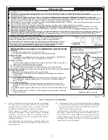
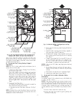
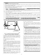
The condensate trap must be removed from the factory-installed
blower shelf location and relocated in selected application location
as shown in Fig. 2 or 10.
To relocate condensate trap from the blower shelf to desired
location, perform the following:
1. Remove 3 tubes connected to condensate trap.
2. Remove trap from blower shelf by gently pushing tabs
inward and rotating trap.
3. Install casing hole filler cap (factory-supplied in loose parts
bag) into blower shelf hole where trap was removed.
WARNING:
CARBON MONOXIDE POISONING
HAZARD
Failure to follow this warning could result in personal
injury or death.
Casing hole filler cap must be installed in blower shelf
hole when condensate trap is relocated to prevent com-
bustion products being drawn in from appliances in the
equipment room.
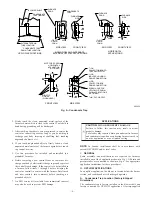
4. Install condensate trap into left-hand side casing hole by
inserting tube connection stubs through casing hole and
rotating until tabs snap into locking position.
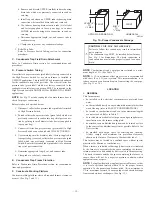
5. Fill unused condensate trap casing holes with plastic filler
caps (factory-supplied in loose parts bag).
B.
Condensate Trap Tubing
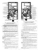
NOTE:
See Fig. 10 or tube routing label on main furnace door to
check for proper connections.
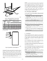
1. Collector Box Drain Tube
a. Install drain tube coupling (factory-supplied in loose
parts bag) into collector box drain tube (blue label)
which was previously connected to condensate trap.
b. Connect large diameter drain tube and clamp (factory-
supplied in loose parts bag) to drain tube coupling,
extending collector box drain tube.
c. Route extended tube (blue label) to condensate trap and
cut to appropriate length.
d. Clamp tube to prevent any condensate leakage.
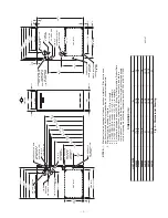
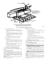
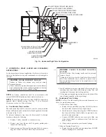
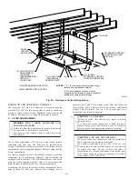
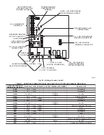
Fig. 10—Horizontal Left Tube Configuration
A01029
CONDENSATE
TRAP
AUXILIARY
"
J
"
BOX
PLUG
CAP
INDUCER HOUSING
DRAIN TUBE (VIOLET)
COLLECTOR BOX
DRAIN TUBE (BLUE)
COLLECTOR BOX TUBE (PINK)
RELOCATE TUBE BETWEEN BLOWER SHELF AND INDUCER HOUSING FOR
040, 060, AND 080 HEATING INPUT FURNACES
COLLECTOR BOX
EXTENSION TUBE
COLLECTOR BOX
DRAIN TUBE
(BLUE AND WHITE STRIPED)
DRAIN TUBE COUPLING
COLLECTOR BOX
TUBE (GREEN)
COLLECTOR
BOX EXTENSION
DRAIN TUBE
—10—
→
Содержание CONDENSING GAS FURNACE 352MAV
Страница 51: ...51...


