


Piping should be pressure and leak tested in accordance with local
and NFGC, national plumbing and gas codes before the furnace
has been connected. In Canada, refer to current edition of
NSCNGPIC. If the pressure exceeds 0.5 psig (14-in. wc), gas
supply pipe must be disconnected from the furnace and capped
before pressure test. If test pressure is equal to or less than 0.5 psig
(14-in. wc), turn off electric shutoff switch located on furnace gas
valve and accessible manual shutoff valve before test.
After all connections have been made, purge lines and check for
leakage.
NOTE:
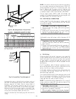
The gas valve inlet pressure tap connection is suitable to
use as test gauge connection providing test pressure DOES NOT
exceed maximum 0.5 psig (14-in. wc) stated on gas valve. (See
Fig. 53.) Piping should be pressure tested in accordance with
NFGC local and national plumbing and gas codes before furnace
is attached. In Canada, refer to current edition of NSCNGPIC.
The gas supply pressure shall be within the maximum and
minimum inlet supply pressures marked on the rating plate with
the furnace burners ON at HI-HEAT and OFF.
VIII.
ELECTRICAL CONNECTIONS
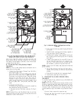
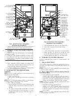
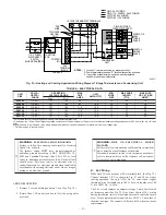
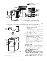
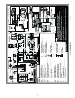
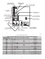
See Fig. 27 and 28 for field wiring diagram showing typical field
115-v and 24-v wiring. Check all factory and field electrical
connections for tightness.
WARNING:
ELECTRICAL SHOCK HAZARD
Failure to follow this warning could result in personal
injury or death.
Blower access door switch opens 115-v power to furnace
control. No component operation can occur. Do not
bypass or close switch with panel removed.
Field-supplied wiring shall conform with the limitations of 63°F
rise.
CAUTION:
UNIT MAY NOT OPERATE
Failure to follow this caution may result in intermittent
unit operation.
Furnace control must be grounded for proper operation or
control will lock out. Control is grounded through
green/yellow wire routed to gas valve C-terminal and
burner box screw.
A.
115-V Wiring
Before proceeding with electrical connections, make certain that
voltage, frequency, and phase correspond to that specified on the
furnace rating plate. Also, check to be sure that service provided
by power supply is sufficient to handle load imposed by this
equipment. Refer to rating plate or Table 4 for equipment electrical
specifications.
For U.S. installations, make all electrical connections in accor-
dance with National Electrical Code (NEC) ANSI/NFPA 70-2002
and any local codes or ordinances that might apply.
For Canadian installations, all electrical connections must be made
in accordance with Canadian Electrical Code CSA C22.1 or
authorities having jurisdiction.
Use a separate branch electrical circuit containing a properly sized
fuse or circuit breaker for this furnace. See Table 4 for wire size
and fuse specifications. A disconnecting means must be located
within sight from and readily accessible to furnace.
NOTE:
Proper polarity must be maintained for 115-v wiring. If
polarity is incorrect, control LED status indicator light will flash
rapidly and furnace will NOT operate.
WARNING:
FIRE HAZARD
Failure to follow this warning could result in intermittent
operation or performance satisfaction.
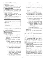
Do not connect aluminum wire between disconnect
switch and furnace. Use only copper wire. (See Fig. 29.)
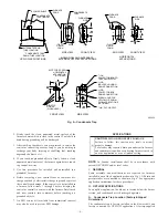
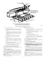
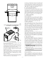
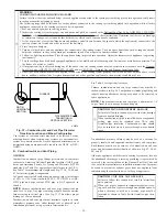
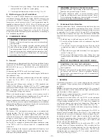
Fig. 25—Removing Bottom Closure Panel
A93047
BOTTOM
CLOSURE
PANEL
FRONT FILLER
PANEL
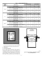
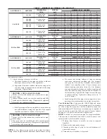
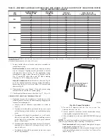
TABLE 3—MAXIMUM CAPACITY OF PIPE*
NOMINAL
IRON
PIPE
SIZE
(IN.)
INTERNAL
DIAMETER
(IN.)
LENGTH OF PIPE (FT)
10
20
30
40
50
1/2
0.622
175
120
97
82
73
3/4
0.824
360
250
200
170
151
1
1.049
680
465
375
320
285
1-1/4
1.380
1400
950
770
660
580
1-1/2
1.610
2100
1460
1180
990
900
* Cubic ft of gas per hr. for gas pressures of 0.5 psig (14–in. wc) or less and
a pressure drop of 0.5–in wc (based on a 0.60 specific gravity gas).
Ref: Table 9.2 NFGC.
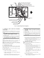
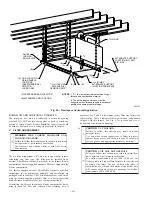
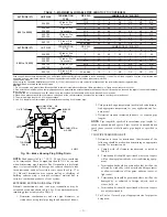
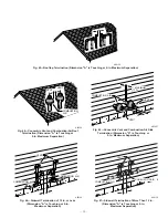
Fig. 26—Typical Gas Pipe Arrangement
A93324
UNION
SEDIMENT
TRAP
MANUAL
SHUTOFF
VALVE
(REQUIRED)
GAS
SUPPLY
—20—
Содержание CONDENSING GAS FURNACE 352MAV
Страница 51: ...51...


